
Zhuqiang Li, Ruifei Zhu, Jingyu Ma, Xiangyu Meng, Dong Wang, Siyan Liu. Airport Detection Method Combined with Continuous Learning of Residual-Based Network on Remote Sensing Image[J]. Acta Optica Sinica, 2020, 40(16): 1628005
- Acta Optica Sinica
- Vol. 40, Issue 16, 1628005 (2020)
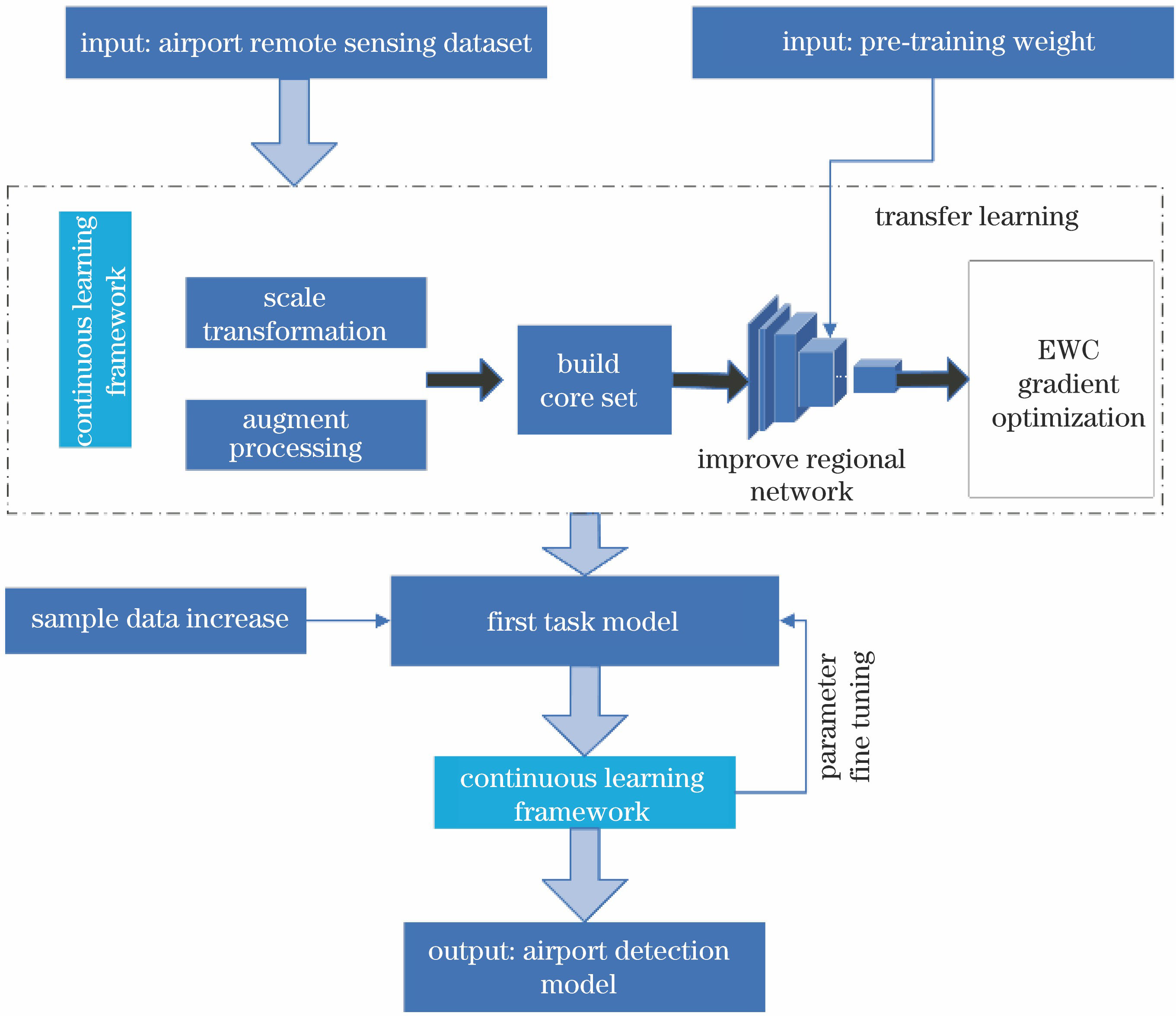
Fig. 1. Flow chart of airport detection method combined with continuous learning of residual-based network
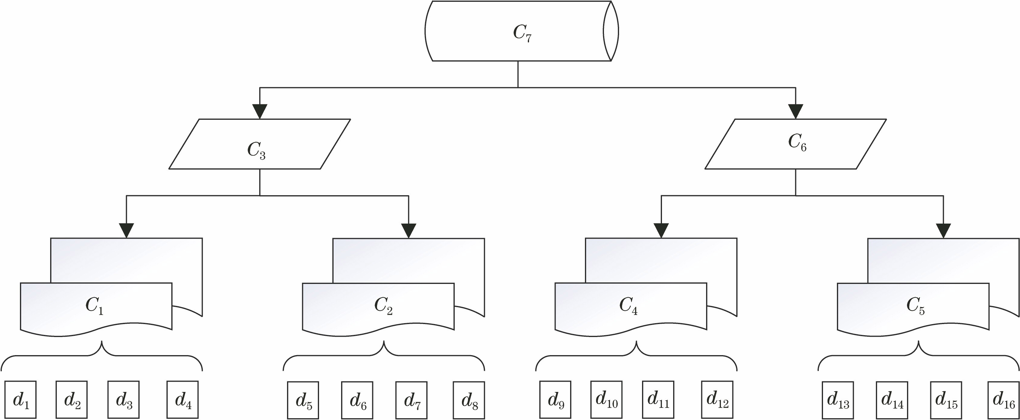
Fig. 2. Constructing airport object core set by binary tree method
Fig. 3. Airport object detection network structure combined with residual block network
Fig. 4. Improve the scale of anchor in RPN for airport object
Fig. 5. Visualization of the feature map of the target in the image by the residual network. (a) Original true color image; (b) feature map from 64 convolution kernels; (c) feature map from 1024 convolution kernels; (d) feature heat map obtained from classification regression and border regression
Fig. 6. Verification set loss function decline curve and accuracy test. (a) Loss value decline curve; (b) accuracy test curve
Fig. 7. Airport object detection results in remote sensing images under different background environments. (a) Test result in hilly area environment; (b) test result in desert environment; (c) test result in an island environment; (d) test result in port environment
Fig. 8. Misclassification caused by background texture similar to airport objects. (a) Bridge facilities; (b) industrial park; (c) highway; (d) structured experimental field
Fig. 9. Airport object detection results under interference conditions. (a) Cloud interference; (b) sweeping incomplete; (c) large difference in object scale in the same image; (d) small airport
Fig. 10. Comparison of airport detection results in continuous learning mode. (a) CLRNet 1st stage detection results under the condition that the target texture shape is similar to the airport; (b) CLRNet 2nd stage detection result under the condition that the target texture shape is similar to the airport; (c) CLRNet 1st stage detection result under background environment interference; (d) CLRNet 2nd stage detection result under background environment interference
|
Table 1. Airport object remote sensing dataset of Jilin-1
|
Table 2. Airport object detection network structure combined with residual block network
|
Table 3. Precision and efficiency of different detection methods for airport object

Set citation alerts for the article
Please enter your email address
© Copyright 2018-2021 | Chinese Laser Press. All Rights Reserved 沪ICP备15018463号-20