• Acta Optica Sinica
  • Vol. 39, Issue 4, 0412013 (2019)
Xiaoyan Li1, Yongfu Wen1、2、*, Haobo Cheng1、2、*, Hengyu Wu1, and Huaying Wang2
Author Affiliations
  • 1 School of Optics and Photonics, Beijing Institute of Technology, Beijing 100081, China
  • 2 Shenzhen Research Institute, Beijing Institute of Technology, Shenzhen, Guangdong 518057, China
  • show less
    DOI: 10.3788/AOS201939.0412013 Cite this Article Set citation alerts
    Xiaoyan Li, Yongfu Wen, Haobo Cheng, Hengyu Wu, Huaying Wang. Interferometric Projection Fourier Transform Profilometry Based on Cube Beam Splitting Prism[J]. Acta Optica Sinica, 2019, 39(4): 0412013 Copy Citation Text show less
    Optical path of FTP measurement system
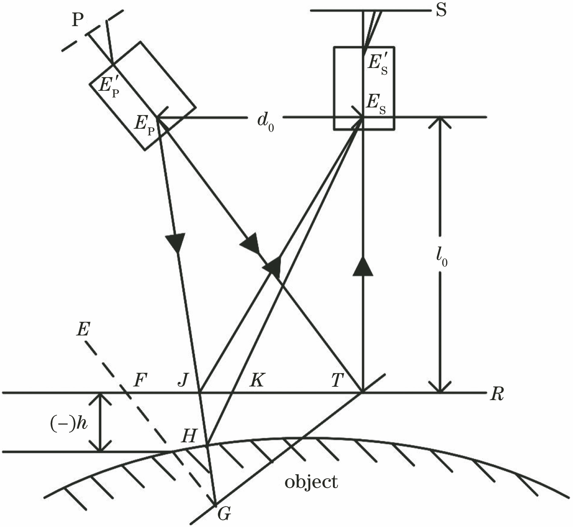
    Fig. 1. Optical path of FTP measurement system
    Schematic of common optical path interference
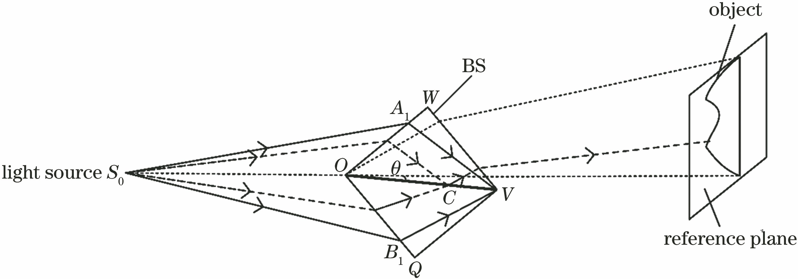
    Fig. 2. Schematic of common optical path interference
    Coordinate analysis of common optical path interference
    Fig. 3. Coordinate analysis of common optical path interference
    Interference patterns. (a) Simulated interference fringe when θ=3.55°; (b) simulated interference fringe when θ=3.57°; (c) simulated interference fringe when θ=3.58°; (d) actual interference fringe when θ=2°; (e) actual interference fringe when θ=3°
    Fig. 4. Interference patterns. (a) Simulated interference fringe when θ=3.55°; (b) simulated interference fringe when θ=3.57°; (c) simulated interference fringe when θ=3.58°; (d) actual interference fringe when θ=2°; (e) actual interference fringe when θ=3°
    Physical diagram of experimental equipment
    Fig. 5. Physical diagram of experimental equipment
    Object to be measured. (a) Physical object and deformed fringe pattern; (b) phase unwrapping pattern
    Fig. 6. Object to be measured. (a) Physical object and deformed fringe pattern; (b) phase unwrapping pattern
    Phase distribution maps of the same row of each calibration plane at different positions. (a) Before unwrapping; (b) after unwrapping
    Fig. 7. Phase distribution maps of the same row of each calibration plane at different positions. (a) Before unwrapping; (b) after unwrapping
    Calibration results of measurement system. (a) Parameter a; (b) parameter b
    Fig. 8. Calibration results of measurement system. (a) Parameter a; (b) parameter b
    Experiment results. (a) Three coordinate machine measurement chart; (b) three-dimensional topography of object; (c) error distribution map
    Fig. 9. Experiment results. (a) Three coordinate machine measurement chart; (b) three-dimensional topography of object; (c) error distribution map
    Calibration plane 9 error analysis. (a) Fringe pattern; (b) fringe pattern in line 300; (c) Fourier spectrum; (d) phase unwrapping pattern
    Fig. 10. Calibration plane 9 error analysis. (a) Fringe pattern; (b) fringe pattern in line 300; (c) Fourier spectrum; (d) phase unwrapping pattern
    Xiaoyan Li, Yongfu Wen, Haobo Cheng, Hengyu Wu, Huaying Wang. Interferometric Projection Fourier Transform Profilometry Based on Cube Beam Splitting Prism[J]. Acta Optica Sinica, 2019, 39(4): 0412013
    Download Citation