• Laser & Optoelectronics Progress
  • Vol. 55, Issue 2, 021301 (2018)
Liheng Wu and Minghong Wang*
Author Affiliations
  • School of Physical Science & Information Engineering, Liaocheng University, Liaocheng, Shandong 252059, China
  • show less
    DOI: 10.3788/LOP55.021301 Cite this Article Set citation alerts
    Liheng Wu, Minghong Wang. Operating Characteristics of Photonic Crystal Filters Based on Micro Resonators[J]. Laser & Optoelectronics Progress, 2018, 55(2): 021301 Copy Citation Text show less
    Influence of different ratios of Q2/Q1 and values of phase detuning factor (ω-ω0)2τ22 on normalized reflectivity. (a) Q2/Q1=0.2; (b) Q2/Q1=0.5; (c) Q2/Q1=1; (d) Q2/Q1=10; (e) Q2/Q1=200; (f) Q2/Q1=600
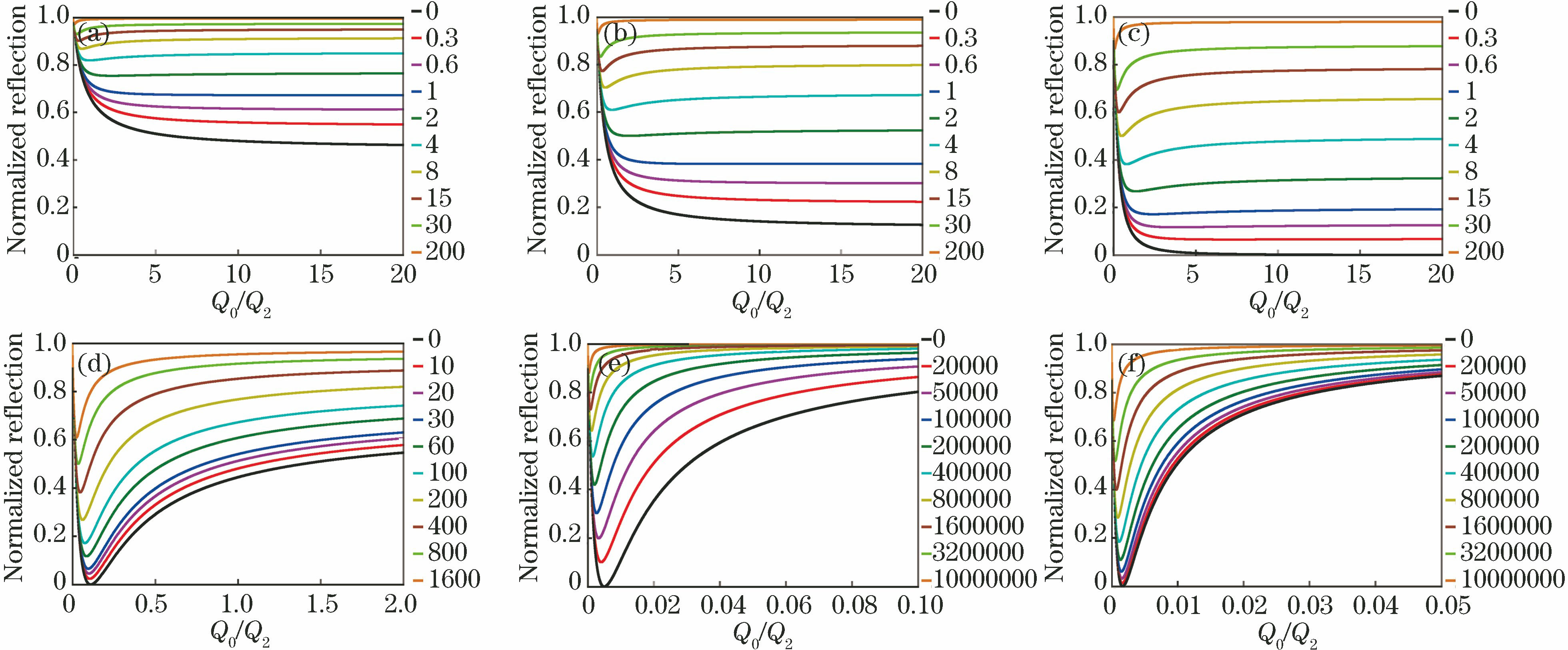
    Fig. 1. Influence of different ratios of Q2/Q1 and values of phase detuning factor (ω-ω0)2τ22 on normalized reflectivity. (a) Q2/Q1=0.2; (b) Q2/Q1=0.5; (c) Q2/Q1=1; (d) Q2/Q1=10; (e) Q2/Q1=200; (f) Q2/Q1=600
    Influence of different ratios of Q2/Q1 and values of phase detuning factor (ω-ω0)2τ22 on normalized loss ratio. (a) Q2/Q1=0.1; (b) Q2/Q1=0.5; (c) Q2/Q1=1; (d) Q2/Q1=10; (e) Q2/Q1=200; (f) Q2/Q1=600
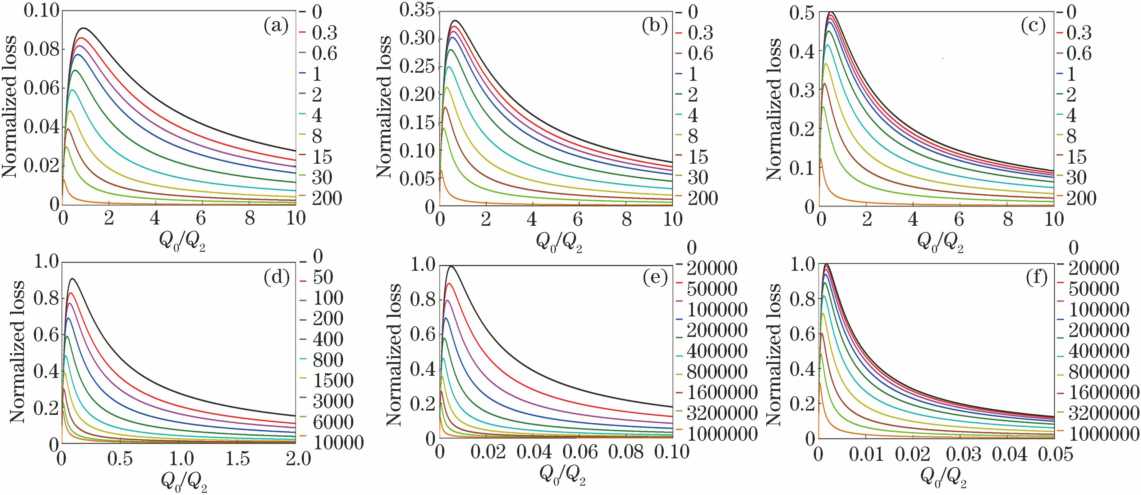
    Fig. 2. Influence of different ratios of Q2/Q1 and values of phase detuning factor (ω-ω0)2τ22 on normalized loss ratio. (a) Q2/Q1=0.1; (b) Q2/Q1=0.5; (c) Q2/Q1=1; (d) Q2/Q1=10; (e) Q2/Q1=200; (f) Q2/Q1=600
    Influence of different ratios of Q2/Q1 and values of phase detuning factor (ω-ω0)2τ22 on normalized transmission. (a) Q2/Q1=0.2; (b) Q2/Q1=0.5; (c) Q2/Q1=1; (d) Q2/Q1=2; (e) Q2/Q1=5; (f) Q2/Q1=10
    Fig. 3. Influence of different ratios of Q2/Q1 and values of phase detuning factor (ω-ω0)2τ22 on normalized transmission. (a) Q2/Q1=0.2; (b) Q2/Q1=0.5; (c) Q2/Q1=1; (d) Q2/Q1=2; (e) Q2/Q1=5; (f) Q2/Q1=10
    Structures of photonic crystal filters based on two types of micro resonators. (a)(c)(e)(g) resonator 1 with an air cavity; (b)(d)(f)(h) resonator 2 with a rod cavity
    Fig. 4. Structures of photonic crystal filters based on two types of micro resonators. (a)(c)(e)(g) resonator 1 with an air cavity; (b)(d)(f)(h) resonator 2 with a rod cavity
    Normalized transmission spectra of photonic crystal filters. (a) Filter Ⅰ; (b) filter Ⅱ; (c) filter Ⅲ; (d) filter Ⅳ
    Fig. 5. Normalized transmission spectra of photonic crystal filters. (a) Filter Ⅰ; (b) filter Ⅱ; (c) filter Ⅲ; (d) filter Ⅳ
    Micro resonator 1Micro resonator 2
    Solid lineriλΔλT /%Dot lineriλΔλT /%
    10.140a1309.01.735.7170.140a1459.53.490.3
    20.145a1314.51.743.1180.145a1467.43.293.4
    30.150a1327.21.662.9190.150a1484.52.897.0
    40.155a1338.51.579.0200.155a1499.62.197.7
    50.160a1347.01.685.9210.160a1510.11.891.0
    60.165a1354.81.687.9220.165a1519.61.687.3
    70.170a1362.21.686.5230.170a1527.91.685.1
    80.175a1364.21.686.4240.175a1529.81.580.2
    90.180a1376.31.681.4250.180a1542.61.554.8
    100.182a1383.11.779.0260.182a1549.51.542.6
    110.190a1389.81.877.3270.190a1555.91.532.5
    120.195a1396.51.577.4280.195a1561.81.524.5
    130.200a1404.82.178.8290.200a1568.91.516.5
    140.205a1420.32.784.4
    150.210a1427.53.288.2
    160.215a1438.73.893.6
    Table 1. Optical parameters of filter Ⅰ
    Micro resonator 1Micro resonator 2
    Solid lineriλΔλT /%Dot lineriλΔλT /%
    10.140a1309.93.699.0160.140a1459.24.499.5
    20.145a1315.53.298.7170.145a1467.14.599.1
    30.150a1328.02.599.5180.150a1485.04.099.3
    40.155a1339.32.399.0190.155a1500.23.199.2
    50.160a1347.62.299.0200.160a1510.62.597.9
    60.165a1355.62.299.4210.165a1520.12.199.4
    70.170a1363.12.499.7210.170a1528.72.099.2
    80.175a1364.82.499.4230.175a1530.62.098.9
    90.180a1377.02.895.9240.180a1543.42.097.4
    100.182a1384.02.994.3250.182a1550.32.094.5
    110.190a1390.93.092.9260.190a1556.72.192.1
    120.195a1397.83.191.7270.195a1562.92.291.9
    130.200a1406.23.091.2280.200a1570.02.290.6
    140.205a1421.92.992.5290.205a1582.32.185.3
    150.210a1429.22.994.3
    Table 2. Optical parameters of filter Ⅱ
    Micro resonator 1Micro resonator 2
    Solid lineriλΔλT /%Dot lineriλΔλT /%
    10.140a1309.92.999.8160.140a1459.24.396.9
    20.145a1315.52.799.9170.145a1467.14.498.3
    30.150a1328.02.499.6180.150a1485.04.199.6
    40.155a1339.22.398.2190.155a1500.23.398.1
    50.160a1347.62.497.0200.160a1510.93.695.9
    60.165a1355.42.595.0210.165a1520.42.299.2
    70.170a1363.12.694.0210.170a1528.71.996.4
    80.175a1364.82.797.2230.175a1530.61.995.4
    90.180a1377.12.995.2240.180a1543.41.895.3
    100.182a1384.03.094.3250.182a1550.31.894.1
    110.190a1391.12.992.4260.190a1556.71.893.3
    120.195a1397.82.994.9270.195a1562.61.992.2
    130.200a1406.22.894.3280.200a1569.72.191.6
    140.205a1421.92.896.8
    150.210a1429.22.897.5
    Table 3. Optical parameters of filter Ⅲ
    Micro resonator 1Micro resonator 2
    Solid lineriλΔλT /%Dot lineriλΔλT /%
    10.140a1308.03.697.9160.140a1459.23.497.0
    20.145a1313.53.899.3170.145a1467.13.698.9
    30.150a1326.63.999.6180.150a1484.24.699.0
    40.155a1338.33.699.4190.155a1500.05.499.4
    50.160a1346.83.299.6200.160a1510.45.498.7
    60.165a1354.82.997.7210.165a1520.25.098.6
    70.170a1362.22.698.7210.170a1528.74.497.9
    80.175a1364.02.698.2230.175a1530.64.397.3
    90.180a1376.02.498.2240.180a1543.43.794.2
    100.182a1382.72.596.4250.182a1550.13.699.9
    110.190a1389.32.695.1260.190a1556.53.697.5
    120.195a1396.02.993.8270.195a1562.43.894.9
    130.200a1404.23.493.7280.200a1569.44.291.5
    140.205a1420.04.994.6290.205a1581.75.288.1
    150.210a1426.85.695.5
    Table 4. Optical parameters of filter Ⅳ
    Liheng Wu, Minghong Wang. Operating Characteristics of Photonic Crystal Filters Based on Micro Resonators[J]. Laser & Optoelectronics Progress, 2018, 55(2): 021301
    Download Citation