
Zhipeng Liu, Zhusong Mei, Defeng Kong, Zhuo Pan, Shirui Xu, Ying Gao, Yinren Shou, Pengjie Wang, Zhengxuan Cao, Yulan Liang, Ziyang Peng, Jiarui Zhao, Shiyou Chen, Tan Song, Xun Chen, Tianqi Xu, Xueqing Yan, Wenjun Ma, "Synchronous post-acceleration of laser-driven protons in helical coil targets by controlling the current dispersion," High Power Laser Sci. Eng. 11, 04000e51 (2023)
- High Power Laser Science and Engineering
- Vol. 11, Issue 4, 04000e51 (2023)
Abstract
1 Introduction
Ion acceleration driven by intense and ultrashort laser pulses[1,2] has attracted increasing attention as it can produce MeV–GeV ions on micrometer scale. The unique properties of laser-driven ions, such as ultra-high peak current[3,4] and small source size[5], are in high demand for applications such as radiography[6], FLASH radiotherapy[7,8], material science[9] and nuclear fusion[10]. Among the acceleration mechanisms proposed so far, the most rigorously studied mechanism is target normal sheath acceleration (TNSA)[11–13]. When an ultra-intense laser pulse irradiates a thin solid target, energetic electrons are generated on its front surface. These hot electrons then penetrate the target and create a substantial charge-separation electric field on the target’s rear surface. Ions can be accelerated in this electric field to high energy in a few micrometers. It has been identified as a robust method that can stably generate proton beams with maximum energy up to several tens of MeV[14]. However, theoretical models[15] and experimental results[16,17] have motivated the scaling law between TNSA accelerated ion beam energy and laser intensity as
To overcome the predicament of TNSA acceleration, Kar et al.[21] proposed and realized a scheme for simultaneous post-acceleration, energy selection and ion collimation by attaching a sub-millimeter-diameter helical coil (HC) normal to the rear side of the metallic target foil. It is a further use of the electrons escaping from the laser-ion acceleration without the need for an extra laser pulse. In typical TNSA, the intense laser pulse irradiates the target surface and creates energetic electrons that partially escape. Electrons have a picosecond-scale duration and charge of a few to hundreds of nC[22]. As the escaping electrons leave a positive charge on the target, a discharge current is driven along the wire at a speed close to c, the speed of light in a vacuum[23,24]. This current has an ultra-high density of μC m–1, which can generate an electromagnetic pulse (EMP) along the wire[25,26]. The helical wire acts as an electromagnetic field (EMF) guide to form an intense electric field with a magnitude of GV/m in the center of the HC[21] to post-accelerate the TNSA proton beam. In a demonstration experiment of HC post-acceleration (HCPA), where a 200 TW laser system was used, the maximum proton energy was increased by 35% (2.7 MeV) using a 7-mm-long HC. Later work by Ahmed et al.[27] highlighted HCPA’s function in beam focusing and energy spectrum modulation. They obtained a highly collimated (<1° divergence angle) and narrow-band (10% energy spread) proton beam at approximately 10 MeV. The energy gain can be more significant with increased laser energy and intensity. Simulations based on a test-particle approach predict that a single HC can boost proton energy by 30 MeV with a PW laser[21]. However, the experimental results showed that the energy gain was not as high as expected: only 12 MeV enhancement was observed[28].
Prolonging the acceleration distance by maintaining the synchronization of the HCPA field and protons would be a practical way to increase the energy gain in experiments. Kar et al.[21] conceived a two-beam laser-triggered HC current, allowing protons to travel through the HC twice, and the maximum energy in the simulation exceeded 100 MeV. This scheme was experimentally implemented by Ferguson et al.[29]. Two laser beams with energies of approximately 50 J and approximately 60 J, respectively, interact with two coil targets sequentially. By precisely controlling the beam injection, the protons were post-accelerated twice with an energy gain of approximately 16 MeV (~8 MeV per stage). Moreover, it was proposed that acceleration can synchronize the electric field and accelerating ions by continuously or stepwise adjusting the pitch and radius of the HC[28]. However, it is difficult to implement this HC structure experimentally.
Sign up for High Power Laser Science and Engineering TOC. Get the latest issue of High Power Laser Science and Engineering delivered right to you!Sign up now
In the above works, the current propagating in the HC was assumed to be dispersionless. As a matter of fact, picosecond transient current has a frequency spectrum as wide as tens of GHz[30–33]. When such a broadband current propagates along an HC, the dispersion affected by coupled inductances and capacitances is nonnegligible. Bardon et al.[34] found that in the simulation, the velocity dispersion of the current leads to progressive modification of HCPA, which may be one of the most important reasons for the termination of acceleration in a long HC. Since previous experiments and simulations did not consider current dispersion, an in-depth investigation of its effect on long-time synchronization between the post-acceleration field and protons is important.
In this paper, we systematically study HCPA considering the dispersion effect by using self-consistent EMF and beam dynamics simulations. We first illustrate the relationship between the dispersed current and electric field and its impact on proton beam dynamics, which provides important insight into HCPA. It is found that the sudden phase reversal of the electric field induced by the current dispersion is the primary reason for the termination of HCPA. Based on our understanding, we propose a two-stage HC structure to compensate for phase change. Under controlled synchronization between the acceleration field and protons, HCPA energy gain is increased by four times.
The paper is structured as follows. Section 2 describes the setup and method of large-scale self-consistent simulations for the current and EMFs. In Section 3, we present the dispersion of current in a straight wire and HC and explain it with a circuit transmission model. In Section 4, we analyze the evolution of the electric field and post-acceleration of protons in a single-stage HC, and demonstrate how current dispersion leads to asynchrony of the electric field and proton beam. In Section 5, we propose a dispersion controlled two-stage HC scheme to enhance energy gain. In Section 6, we discuss the scheme using a multi-stage HC (more than two), and find that additional stages are not beneficial for further energy enhancement. Section 7 summarizes our results.
2 Simulation method
Several numerical simulation methods of HCPA have been reported previously. Jiang et al.[35] executed particle-in-cell (PIC) simulations of the laser’s interaction with an ionized tens-of-micrometers solenoid target. However, these explicit PIC simulations would be unacceptable for such a large HC target (a few centimeters) due to computational limitations. Ahmed et al.[27,28] and Kar et al.[21,36] used the particle-tracing code to investigate proton dynamics, where EMP propagation in the HC is treated as a transverse electromagnetic (TEM) mode. The phase velocity and group velocity of the EMP are equal and independent of frequency, and the HC is considered a dispersionless medium. Bardon et al.[34] used finite-difference time-domain (FDTD) codes[37,38] to simulate the current propagation through the HC, which is a suitable approach to simulate the EMF at full-scale (nanosecond and centimeter scales). However, their simulations lacked particle dynamics analysis to reveal the effect of velocity dispersion on post-acceleration.
Here, we employ the CST particle studio suite[39], a method that combines the FDTD and the PIC codes to simulate the EMFs and beam dynamics in HCPA. The PIC simulations initialize the velocity and position of the charged particles, and Maxwell’s equations are solved by using the FDTD methods to obtain the EMFs efficiently. The EMFs and the particle dynamics are self-consistently described because all the terms in Maxwell’s equations are retained in the equation scheme[40]. The generation of fast electrons and protons caused by the laser–plasma interaction (LPI) at the irradiation spot, which may require explicit PIC simulation, is simplified as particle source emission with energy distribution and total number subject to the interaction mechanism[23]. As a result, the discharged current will be excited spontaneously and propagate following Maxwell’s equations. The interaction between the emitted particles and the generated EMFs is self-consistent, and both spatial-temporal profiles of the EMFs and proton dynamics can be specified.
To make the simulation more realistic, we perform full-scale simulations in time and space at the nanosecond and centimeter scales. The simulation configurations are shown in Figure 1(a). The foil target (Au, 10 μm thickness) is coaxially attached to the HC (aluminum, 100 μm wire diameter). All adjacent structures touch each other and are connected to a pure copper holder at the end to form a current path. All the materials are set as lossy metal, where the electrical conductivity and resistance are determined by the specific materials. Surface permittivity is considered in lossy metal as a surface impedance and skin effect. Nonlinearity is higher than the third-order and susceptibility is described as true third-order tensors in CST code[41]. The solver’s frequency range is 0–100 GHz. The components of the target, coil and holder are meshed in high density with the cell size
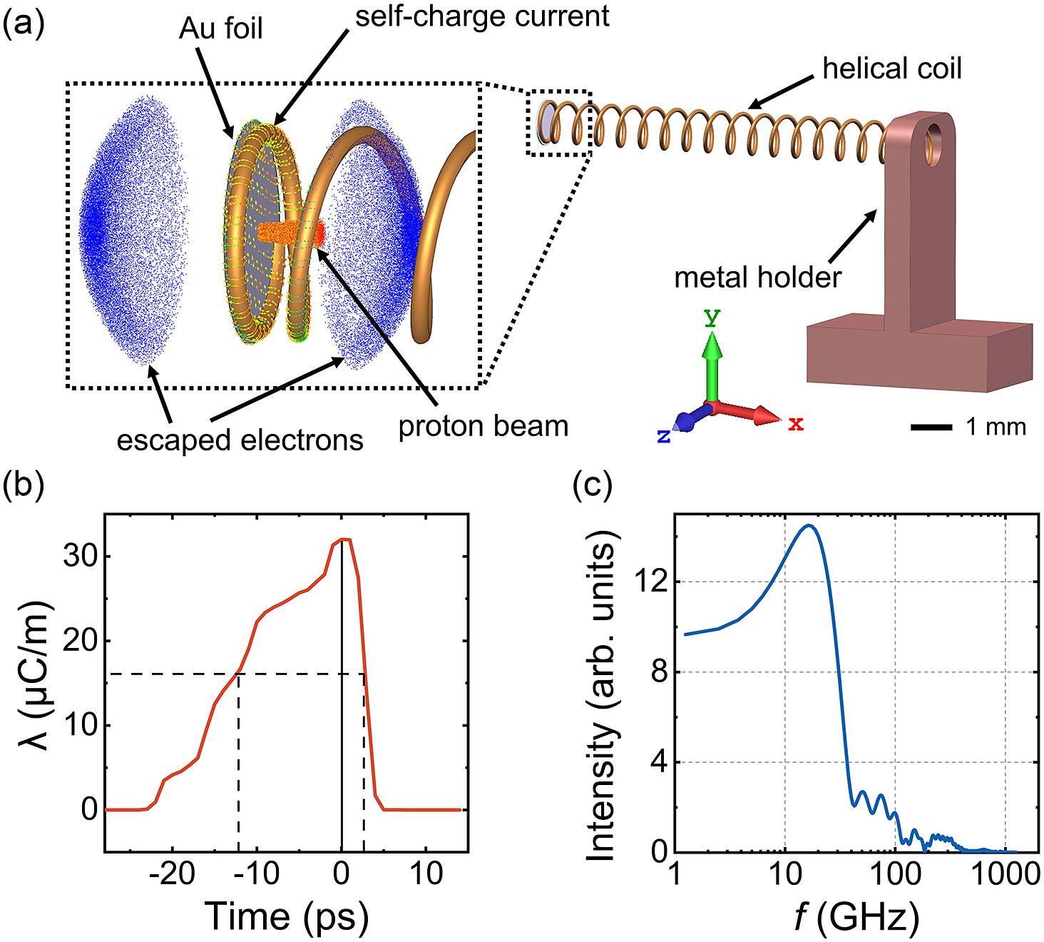
Figure 1.(a) Simulation setup of HC target configurations. (b) Self-discharged current generated by the emitted particles. (c) Spectrum of the current pulse from fast Fourier transform (FFT).
3 Dispersion of a transient current in a straight wire and a helical coil
Firstly, we simulate the propagation of a transient current on a straight Al wire. Figure 2(a) shows the simulation result of the current as a function of time. The front of the current propagates along the wire near the speed of light in a vacuum. As it propagates in the x direction, the tail of the current grows due to dispersion. This can be numerically explained by the circuit transmission model[49]. To help clearly understand the impact of current dispersion, we assume that the transmission line is lossless, where resistance and conductance are set to zero. The nonlinear permittivity between the wire surface and the vacuum is ignored. The propagation of current can be described by the telegraph equation[50]:
where La and Ca are the equivalent inductance and capacitance of the HC, which are given by Kino and Paik[52] as follows:
where
By solving Equation (5) numerically, we can obtain the surface velocity
![]()
Figure 2.(a) The spatial-temporal distribution of the current on the straight aluminum wire, where the black dashed line refers to the speed of light. (b) Dependence of the surface current velocities on the ratio of the wavelength to the coil diameter ( ), with different radii and pitches in the HC and straight wire. The
Figure 2(c) shows the spatial-temporal distribution of the current in the HC with pitch
4 Evolution of the electric field and the post-acceleration of protons in a single-stage helical coil
The traveling transient current builds a transient electric field around the wire. In the case of the HC, the field near the center of the coil has a substantial longitudinal component accelerating the protons from the thin foil. In HCPA ignoring current dispersion, Ahmed et al.[28] proposed the scheme of stepwise increasing the pitch to handle the synchronization of the electric field and accelerating protons. In their simulation, protons can maintain synchronous acceleration over considerable distances. In our simulation, where current dispersion is considered as it should be, we find that the electric field is constantly changing. Figure 3(a) shows the longitudinal electric field on the central axis of the HC (labeled as Ex) obtained from simulations with
![]()
Figure 3.(a) Snapshot of the longitudinal electric field on the central axis of the HC at 60, 120 and 180 ps. The red balls represent the positions of protons with cut-off energy at different times. (b) Spatial-temporal distribution of the longitudinal electric field in an HC, with the mark of the extreme points of positive fields (green dashed lines).
In Figure 3(b), the green dashed lines mark the extreme point of the positive Ex in the spatial-temporal distribution. The apparent longitudinal velocity of the positive electric field is fitted to
We investigate the post-acceleration process of the protons in the evolving electric field in the HC with the constant pitch and radius,
![]()
Figure 4.(a) Snapshots of proton distributions in phase space (
We have simulated the energy gains of protons with different input energies from 20 to 30 MeV in the HC, as shown in Figure 5(a). Protons in a wider energy range similarly undergo acceleration and deceleration. Figure 5(b) shows the Ex distribution and the proton trajectories. It is shown that higher-energy protons will be ‘caught up’ by the negative electric field later, and will obtain higher energy gain, but it is still a faint enhancement. The protons cannot undergo continuous acceleration even if their initial kinetic energy is 30 MeV with injected velocities close to 1.2βc.
![]()
Figure 5.(a) Energy gains of traveling protons in the HC with different input energies. (b) The spatial-temporal distribution of
In summary, the deceleration stage resulting from the current dispersion drastically undermines the energy gain in the post-acceleration. The second positive electric field is not efficiently utilized. The methods, by continuously or stepwise adjusting the pitch and radius of the HC to extend the accelerated distance[28], cannot eliminate current dispersion and only obtain short-time acceleration. New schemes that consider the current dispersion and can maintain synchronous acceleration for a long time are essential for high-gain post-acceleration.
5 Enhanced post-acceleration in two-stage helical coil post-acceleration
To overcome the problems caused by the current dispersion, we propose a scheme where a two-stage HC is employed, to achieve synchronous acceleration for a long time. The geometry of the two-stage HC is shown in Figure 6(a), where the pitch and radius of the HC are the same as those of the single-stage HC. There is a straight wire between the two coils as the ‘drift section’. After the acceleration in the first HC, as shown above, the most energetic protons travel faster than the positive pole of the field and slide into the negative field. In the drift section, the current dispersion becomes milder, and the velocity of the positive current is higher than that of the protons. It is therefore possible to compensate for the phase sliding with appropriate parameters. After the drift section, the protons are in the positive field and begin to be accelerated again in the second HC.
![]()
Figure 6.(a) The structure of a single-stage HC and a two-stage HC. (b) The spatial-temporal distribution of the current in the two-stage HC. (c), (d) The temporal profiles of the current pulses at 4 and 8 mm in the case of single- and two-stage HCs, respectively.
The drift section is introduced at the position of
The spatial-temporal distribution of the electric field Ex is illustrated in Figure 7(a), where the peaks of the positive field are marked by the green dashed lines. The positive electric fields in the first and second stages are seamlessly connected by a straight velocity line of 1.2βc because the electric field after the drift section is more forward. Figure 7(b) shows the distributions of Ex and the position of the protons with cut-off energy at different times. We need to highlight that the initial positive electric field (60 ps) has been reduced, and the protons can only be subsequently synchronized with the next increased positive electric field. At 240 ps in the case of the single-stage HC, the electric field is relatively backward. The proton is in a negative electric field and is 3.2 mm away from the positive electric field. In the case of the two-stage HC, protons are synchronized with the positive electric field. The drift section in the two-stage HC acts to make the electric field propagate much faster than the protons, and the delayed positive peak is thus able to catch the protons again.
![]()
Figure 7.(a) Longitudinal electric field in the two-stage HC, where the black dashed line indicates the velocity mark of 1.2
Figure 8(a) shows the protons’ distributions in phase space and Ex in the two-stage HC. The high-energy protons are kept in sync with the positive electric field at 60, 240 and 360 ps. As a result, their cut-off energies are significantly improved. Figure 8(b) shows the witnessed Ex of the most energetic protons in their coordinate frames. They are accelerated in the first HC, and the cut-off energy is increased to 29.1 MeV at a position of
![]()
Figure 8.(a) Snapshots of the proton distributions in phase space (
It should be noted that the acceleration distance of the protons in the second stage is much longer than in the first stage. In the first stage, the amplitude of the positive electric field is maximum at the beginning (Figure 7(b)). The positive electric field will decrease due to the current dispersion, which is a half-cycle process. In the second-stage HC, the second positive electric field pulse becomes strong and then decreases, which is a full-cycle process. As shown in Figure 6(b), the pulse duration of the current in the second stage is greater than that in the first stage due to the current dispersion. The evolution of the dispersion current will become more stable as the pulse duration expands, as demonstrated by Bardon et al.[34]. Therefore, the acceleration of the protons in the second stage can be more stable.
The position and length of the drift section must be carefully designed to compensate for the delay of the electric field due to the phase reversal. We illustrate snapshots of the Ex of the single-stage HC at different times and mark the spatial positions of protons at cut-off energy in Figure 9(a). The protons represented by the red balls have energies of 28.3, 28.5 and 29.1 MeV at 90, 97 and 102 ps, respectively. At 96 ps, when the most energetic protons are at
![]()
Figure 9.(a) Snapshots of the current distributions and the positions of protons at cut-off energy in the single-stage HC at 90, 96 and 102 ps. (b) Energy gain by varying the helical length of the single-stage HC and the drift length of the two-stage HC. (c) Spectrum of the input protons (black line); spectrum after a single-stage HC of 8 mm (green dashed line) and 20 mm (blue dashed line); spectrum after a two-stage HC (red line).
We also vary the length of the single-stage HC and the drift section in the two-stage HC to investigate their energy gains, where the total length of the two-stage HC is kept at 32 mm. As shown in Figure 9(b), the maximum energy gain of the single-stage acceleration is 4.7 MeV with an HC length of 8 mm, which is already longer than the actual acceleration distance of the protons. The maximum energy gain of the two-stage HC reaches 20.1 MeV when the drift length is 3.8 mm. Moreover, energy gain above 15 MeV can be achieved within ±1 mm deviation from the optimum drift length, making it robust for experiments. Figure 9(c) shows the simulated spectrum of the post-accelerated protons after the single-stage and two-stage HC. The primary protons are exponentially distributed with cut-off energy of 25 MeV. It is increased to 29.7 MeV with a single-stage HC of 8 mm length, and the cut-off energy is increased by 19%. Further increasing the length of the single-stage HC to 20 mm does not result in an increase in the energy but rather a reduction. By using the two-stage HC scheme, the acceleration distance can be substantially increased. With the two-stage length of 32 mm, the proton cut-off energy can be increased to 45.1 MeV, an 80.4% increase in cut-off energy, which is four times that of a single-stage HC.
We envision that the two-stage HC scheme can be used for a petawatt-class femtosecond laser to generate high-energy protons for radiotherapy applications. As shown in Figure 10(a), the scaling for escape electron charge as a function of incident laser intensity can be obtained from the model reported by Poye et al.[46]. The scaling for the cut-off energy of the protons is derived from the model of Dover et al.[47]. The red circles mark the hundreds-of-terawatt laser that we have simulated in the above works. We apply a laser pulse width of 40 fs, a focal spot radius of 6 μm and an absorption coefficient of 40% in the models. It is hoped that a total escape electron charge of 300 nC and a proton cut-off energy of 60 MeV will be generated by a petawatt-class laser with intensity of
![]()
Figure 10.(a) Expected target charge of escaped electrons in the logarithmic scale calculated from the model as a function of laser intensity (blue solid line). The green dashed line shows the cut-off energy of laser-driven protons against laser intensity. The requirements of the hundreds-of-terawatts laser and the petawatt laser in the simulations are marked with red circles and rhombuses, respectively. (b) Spectrum of the input protons in the simulations with the petawatt laser (black line); spectrum after a single-stage HC (blue line); spectrum after a two-stage HC (red line). The lengths of the single-stage HC and two-stage HC are 10 and 40 mm, with  and
and  , respectively, and the drift length is 6.6 mm.
6 Discussion
The above results unambiguously demonstrate that a two-stage HC with a drift section is very beneficial for proton energy enhancement. An interesting question would be the following: given that current dispersion and phase change could be controlled by the drift section, can a multi-stage scheme (over two stages) be applied to achieve longer distance synchronization and thus continue to boost proton energy?
We find that the energy enhancement in a multi-stage HC will be constrained by the impedance mismatch between the coils and the drift sections. The impedance mismatch will cause a current reflection at the connection point between the coil and the drift section, as shown in Figure 11(a). The reflected current will superimpose on the original pulse to form a pulse train, called reflection ringing (RR)[55]. We first conduct simulations of the current and the electric field in a structure consisting of three HC segments based on the hundreds-of-terawatts laser. The current will be reflected when it enters the drift section from the coil, resulting in disruption and weakening of the current (see Figure 11(b)). In the third HC, the current distribution will become much more complex due to the development of dispersion and RR.
![]()
Figure 11.(a) Scheme of the reflection ringing of a three-stage HC structure. (b) Spatial-temporal distribution of the current in a three-stage HC. (c) Spatial-temporal distribution of
The longitudinal electric field is also affected. We build the three-stage HC on the basis of the two-stage HC according to the strategy previously described. The second drift section is introduced when the third positive electric field equals the second one. The delay between each positive electric field could be compensated as they coincide with the black dashed line in Figure 11(c). The synchronous acceleration of protons is maintained. However, the waveform of the electric field becomes more turbulent, and its strength decreases simultaneously. We check the energy gain from single-stage to four-stage HCs separately in Figure 11(d). The blue curve shows the maximum strength of Ex in different stages. It is observed that the electric field decreases rapidly as the number of stages increases, with only 0.5 GV/m in the fourth HC. As a result, the energy gain can be significantly increased to 20.1 MeV in the second HC, but modestly increased to 22 or 23.2 MeV in the third or fourth HC, even though the total HC length has been doubled.
7 Conclusion
We demonstrate a dispersion-controlled scheme to enhance the energy of post-acceleration protons using a two-stage HC structure. The cut-off energy is improved from 25 to 45.1 MeV with a hundreds-of-terawatts laser, four times higher than that of the single-stage HC. Over 100 MeV protons can be obtained using a petawatt laser. Based on the self-consistent simulations and the circuit transmission model, we reveal for the first time in detail how the transient current pulses disperse in an HC, causing phase sliding and reversal in the electric field, and how the protons become desynchronous with the acceleration field. With a two-stage HC structure, the current travels faster in the drift section and can compensate for the dispersion-induced delay, thus enabling the proton and accelerated field to synchronize again. In conclusion, the two-stage scheme is a simple and practical way to control the current dispersion of HCPA to enhance the energy gain of laser-driven ions, which is promising for the application of oncological therapy[56].
References
[1] H. Daido, M. Nishiuchi, A. S. Pirozhkov. Rep. Prog. Phys., 75, 056401(2012).
[2] A. Macchi, M. Borghesi, M. Passoni. Rev. Mod. Phys., 85, 751(2013).
[3] J. Badziak. Opto-Electron. Rev., 15, 1(2007).
[4] M. Borghesi, J. Fuchs, S. V. Bulanov, A. J. Mackinnon, P. K. Patel, M. Roth. Fusion Sci. Technol., 49, 412(2006).
[5] F. Nurnberg, M. Schollmeier, E. Brambrink, A. Blazevic, D. C. Carroll, K. Flippo, D. C. Gautier, M. Geissel, K. Harres, B. M. Hegelich, O. Lundh, K. Markey, P. McKenna, D. Neely, J. Schreiber, M. Roth. Rev. Sci. Instrum., 80, 033301(2009).
[6] J. R. Rygg, F. H. Seguin, C. K. Li, J. A. Frenje, M. J. Manuel, R. D. Petrasso, R. Betti, J. A. Delettrez, O. V. Gotchev, J. P. Knauer, D. D. Meyerhofer, F. J. Marshall, C. Stoeckl, W. Theobald. Science, 319, 1223(2008).
[7] F. Kroll, F. E. Brack, C. Bernert, S. Bock, E. Bodenstein, K. Brüchner, T. E. Cowan, L. Gaus, R. Gebhardt, U. Helbig, L. Karsch, T. Kluge, S. Kraft, M. Krause, E. Lessmann, U. Masood, S. Meister, J. Metzkes-Ng, A. Nossula, J. Pawelke, J. Pietzsch, T. Püschel, M. Reimold, M. Rehwald, C. Richter, H. P. Schlenvoigt, U. Schramm, M. E. P. Umlandt, T. Ziegler, K. Zeil, E. Beyreuther. Nat. Phys., 18, 316(2022).
[8] J. Han, Z. Mei, C. Lu, J. Qian, Y. Liang, X. Sun, Z. Pan, D. Kong, S. Xu, Z. Liu. Front. Cell Dev. Biol., 9, 672929(2021).
[9] M. Barberio, M. Scisciò, S. Vallières, F. Cardelli, S. Chen, G. Famulari, T. Gangolf, G. Revet, A. Schiavi, M. Senzacqua. Nat. Commun., 9, 372(2018).
[10] D. Kong, S. Xu, Y. Shou, Y. Gao, Z. Mei, Z. Pan, Z. Liu, Z. Cao, Y. Liang, Z. Peng, P. Wang, D. Luo, Y. Li, Z. Li, H. Xie, G. Zhang, W. Luo, J. Zhao, S. Chen, Y. Geng, Y. Zhao, J. Xue, X. Yan, W. Ma. Laser Part. Beams, 2022, 1(2022).
[11] P. Mora. Phys. Rev. Lett., 90, 185002(2003).
[12] D. Margarone, O. Klimo, I. J. Kim, J. Prokupek, J. Limpouch, T. M. Jeong, T. Mocek, J. Psikal, H. T. Kim, J. Proska, K. H. Nam, L. Stolcova, I. W. Choi, S. K. Lee, J. H. Sung, T. J. Yu, G. Korn. Phys. Rev. Lett., 109, 234801(2012).
[13] F. Wagner, O. Deppert, C. Brabetz, P. Fiala, A. Kleinschmidt, P. Poth, V. A. Schanz, A. Tebartz, B. Zielbauer, M. Roth, T. Stohlker, V. Bagnoud. Phys. Rev. Lett., 116, 205002(2016).
[14] N. P. Dover, M. Nishiuchi, H. Sakaki, K. Kondo, H. F. Lowe, M. A. Alkhimova, E. J. Ditter, O. C. Ettlinger, A. Y. Faenov, M. Hata, G. S. Hicks, N. Iwata, H. Kiriyama, J. K. Koga, T. Miyahara, Z. Najmudin, T. A. Pikuz, A. S. Pirozhkov, A. Sagisaka, U. Schramm, Y. Sentoku, Y. Watanabe, T. Ziegler, K. Zeil, M. Kando, K. Kondo. High Energy Density Phys., 37, 100847(2020).
[15] J. Schreiber, F. Bell, F. Gruner, U. Schramm, M. Geissler, M. Schnurer, S. Ter-Avetisyan, B. M. Hegelich, J. Cobble, E. Brambrink, J. Fuchs, P. Audebert, D. Habs. Phys. Rev. Lett., 97, 045005(2006).
[16] E. L. Clark, K. Krushelnick, M. Zepf, F. N. Beg, M. Tatarakis, A. Machacek, M. I. Santala, I. I. Watts, P. A. Norreys, A. E. Dangor. Phys. Rev. Lett., 85, 1654(2000).
[17] M. Alien, Y. Sentoku, P. Audebert, A. Blazevic, T. Cowan, J. Fuchs, J. C. Gauthier, M. Geissel, M. Hegelich, S. Karsch, E. Morse, P. K. Patel, M. Roth. Phys. Plasmas, 10, 3283(2003).
[18] L. Robson, P. T. Simpson, R. J. Clarke, K. W. D. Ledingham, F. Lindau, O. Lundh, T. McCanny, P. Mora, D. Neely, C. G. Wahlstrom, M. Zepf, P. McKenna. Nat. Phys., 3, 58(2007).
[19] J. Fuchs, P. Antici, E. D’Humieres, E. Lefebvre, M. Borghesi, E. Brambrink, C. A. Cecchetti, M. Kaluza, V. Malka, M. Manclossi, S. Meyroneinc, P. Mora, J. Schreiber, T. Toncian, H. Pepin, R. Audebert. Nat. Phys., 2, 48(2006).
[20] H. Schwoerer, S. Pfotenhauer, O. Jackel, K. U. Amthor, B. Liesfeld, W. Ziegler, R. Sauerbrey, K. W. Ledingham, T. Esirkepov. Nature, 439, 445(2006).
[21] S. Kar, H. Ahmed, R. Prasad, M. Cerchez, S. Brauckmann, B. Aurand, G. Cantono, P. Hadjisolomou, C. L. S. Lewis, A. Macchi, G. Nersisyan, A. P. L. Robinson, A. M. Schroer, M. Swantusch, M. Zepf, O. Willi, M. Borghesi. Nat. Commun., 7, 10792(2016).
[22] J.-L. Dubois, F. Lubrano-Lavaderci, D. Raffestin, J. Ribolzi, J. Gazave, A. C. La Fontaine, E. d’Humières, S. Hulin, P. Nicolaï, A. Poyé. Phys. Rev. E, 89, 013102(2014).
[23] S. Tokita, S. Sakabe, T. Nagashima, M. Hashida, S. Inoue. Sci. Rep., 5, 8268(2015).
[24] P. McKenna, D. C. Carroll, R. J. Clarke, R. G. Evans, K. W. Ledingham, F. Lindau, O. Lundh, T. McCanny, D. Neely, A. P. Robinson, L. Robson, P. T. Simpson, C. G. Wahlstrom, M. Zepf. Phys. Rev. Lett., 98, 145001(2007).
[25] F. Consoli, V. T. Tikhonchuk, M. Bardon, P. Bradford, D. C. Carroll, J. Cikhardt, M. Cipriani, R. J. Clarke, T. E. Cowan, C. N. Danson. High Power Laser Sci. Eng., 8, e22(2020).
[26] H. B. Zhuo, S. J. Zhang, X. H. Li, H. Y. Zhou, X. Z. Li, D. B. Zou, M. Y. Yu, H. C. Wu, Z. M. Sheng, C. T. Zhou. Phys. Rev. E, 95, 013201(2017).
[27] H. Ahmed, S. Kar, G. Cantono, P. Hadjisolomou, A. Poye, D. Gwynne, C. Lewis, A. Macchi, K. Naughton, G. Nersisyan. Sci. Rep., 7, 10891(2017).
[28] H. Ahmed, P. Hadjisolomou, K. Naughton, A. Alejo, S. Brauckmann, G. Cantono, S. Ferguson, M. Cerchez, D. Doria, J. Green, D. Gwynne, T. Hodge, D. Kumar, A. Macchi, R. Prasad, O. Willi, M. Borghesi, S. Kar. Sci. Rep., 11, 699(2021).
[29] S. Ferguson, P. Martin, H. Ahmed, E. Aktan, M. Alanazi, M. Cerchez, D. Doria, J. S. Green, B. Greenwood, B. Odlozilik, O. Willi, M. Borghesi, S. Kar. New J. Phys., 25, 013006(2023).
[30] A. Poye, J. L. Dubois, F. Lubrano-Lavaderci, E. D’Humieres, M. Bardon, S. Hulin, M. Bailly-Grandvaux, J. Ribolzi, D. Raffestin, J. J. Santos, P. Nicolai, V. Tikhonchuk. Phys. Rev. E, 92, 043107(2015).
[31] H. Ahmed, S. Kar, A. Giesecke, D. Doria, G. Nersisyan, O. Willi, C. Lewis, M. Borghesi. High Power Laser Sci. Eng., 5, e4(2017).
[32] E. Aktan, H. Ahmed, B. Aurand, M. Cerchez, A. Poye, P. Hadjisolomou, M. Borghesi, S. Kar, O. Willi, P. Prasad. Phys. Plasmas, 26, 070701(2019).
[33] K. Quinn, P. A. Wilson, C. A. Cecchetti, B. Ramakrishna, L. Romagnani, G. Sarri, L. Lancia, J. Fuchs, A. Pipahl, T. Toncian, O. Willi, R. J. Clarke, D. Neely, M. Notley, P. Gallegos, D. C. Carroll, M. N. Quinn, X. H. Yuan, P. McKenna, T. V. Liseykina, A. Macchi, M. Borghesi. Phys. Rev. Lett., 102, 194801(2009).
[34] M. Bardon, J. G. Moreau, L. Romagnani, C. Rousseaux, M. Ferri, F. Lefevre, I. Lantuejoul, B. Etchessahar, S. Bazzoli, D. Farcage, H. Maskrot, F. Serres, M. Chevrot, E. Loyez, E. Veuillot, W. Cayzac, B. Vauzour, G. Boutoux, G. Sary, A. C. La Fontaine, L. Gremillet, A. Poye, E. D. Humieres, V. T. Tikhonchuk. Plasma Phys. Controll. Fusion, 62, 125019(2020).
[35] K. Jiang, C. T. Zhou, T. W. Huang, L. B. Ju, C. N. Wu, L. Li, H. Zhang, S. Z. Wu, T. X. Cai, B. Qiao, M. Y. Yu, S. C. Ruan. Plasma Phys. Controll. Fusion, 61, 075004(2019).
[36] S. Kar, H. Ahmed, G. Nersisyan, S. Brauckmann, F. Hanton, A. L. Giesecke, K. Naughton, O. Willi, C. L. S. Lewis, M. Borghesi. Phys. Plasmas, 23, 055711(2016).
[37] D. M. Sullivan. Electromagnetic Simulation Using the FDTD Method(2013).
[38] O. Cessenat. , ().(2013). arXiv:1301.4539
[39] H. Spachmann, U. Becker. Nucl. Instrum. Methods Phys. Res. Sect. A, 558, 50(2006).
[40] W. Kuropka, F. Mayet, R. Aßmann, U. Dorda. Nucl. Instrum. Methods Phys. Res. Sect. A, 909, 193(2018).
[41] https://www.3ds.com/products-services/simulia/products/cst-studio-suite/
[42] A. J. Mackinnon, Y. Sentoku, P. K. Patel, D. W. Price, S. Hatchett, M. H. Key, C. Andersen, R. Snavely, R. R. Freeman. Phys. Rev. Lett., 88, 215006(2002).
[43] M. Tampo, S. Awano, P. R. Bolton, K. Kondo, K. Mima, Y. Mori, H. Nakamura, M. Nakatsutsumi, R. B. Stephens, K. A. Tanaka, T. Tanimoto, T. Yabuuchi, R. Kodama. Phys. Plasmas, 17, 073110(2010).
[44] M. Afshari, J. Hornung, A. Kleinschmidt, P. Neumayer, D. Bertini, V. Bagnoud. AIP Adv., 10, 035023(2020).
[45] D. A. Maclellan, D. C. Carroll, R. J. Gray, N. Booth, B. Gonzalez-Izquierdo, H. W. Powell, G. G. Scott, D. Neely, P. McKenna. Laser Part. Beams, 31, 475(2013).
[46] A. Poye, S. Hulin, M. Bailly-Grandvaux, J. L. Dubois, J. Ribolzi, D. Raffestin, M. Bardon, F. Lubrano-Lavaderci, E. D’Humieres, J. J. Santos, P. Nicolai, V. Tikhonchuk. Phys. Rev. E, 91, 043106(2015).
[47] N. P. Dover, M. Nishiuchi, H. Sakaki, K. Kondo, M. A. Alkhimova, A. Y. Faenov, M. Hata, N. Iwata, H. Kiriyama, J. K. Koga, T. Miyahara, T. A. Pikuz, A. S. Pirozhkov, A. Sagisaka, Y. Sentoku, Y. Watanabe, M. Kando, K. Kondo. Phys. Rev. Lett., 124, 084802(2020).
[48] A. Poyé, S. Hulin, J. Ribolzi, M. Bailly-Grandvaux, F. Lubrano-Lavaderci, M. Bardon, D. Raffestin, J. Santos, V. Tikhonchuk. Phys. Rev. E, 98, 033201(2018).
[49] T. Itoh, C. Caloz. Electromagnetic Metamaterials: Transmission Line Theory and Microwave Applications(2005).
[50] S. Ramo, J. R. Whinnery, T. Van Duzer. Fields and Waves in Communication Electronics(1994).
[51] E. Afshari, H. S. Bhat, A. Hajimiri, J. E. Marsden. J. Appl. Phys., 99, 054901(2006).
[52] G. S. Kino, S. F. Paik. J. Appl. Phys., 33, 3002(1962).
[53] C. N. Danson, C. Haefner, J. Bromage, T. Butcher, J. C. F. Chanteloup, E. A. Chowdhury, A. Galvanauskas, L. A. Gizzi, J. Hein, D. I. Hillier, N. W. Hopps, Y. Kato, E. A. Khazanov, R. Kodama, G. Korn, R. X. Li, Y. T. Li, J. Limpert, J. G. Ma, C. H. Nam, D. Neely, D. Papadopoulos, R. R. Penman, L. J. Qian, J. J. Rocca, A. A. Shaykin, C. W. Siders, C. Spindloe, S. Szatmari, R. M. G. M. Trines, J. Q. Zhu, P. Zhu, J. D. Zuegel. High Power Laser Sci. Eng, e54(2019).
[54] K. D. Wang, K. Zhu, M. J. Easton, Y. J. Li, C. Lin, X. Q. Yan. Phys. Rev. Accel. Beams, 23, 111302(2020).
[55] Y. Chung, M. Cho, H. Lim. IEEE Trans. Vehicular Technol., 71, 9375(2022).
[56] J. Fuchs, P. Audebert, M. Borghesi, H. Pépin, O. Willi. C. R. Phys, 10, 176(2009).


Set citation alerts for the article
Please enter your email address

© Copyright 2018-2021 | Chinese Laser Press. All Rights Reserved 沪ICP备15018463号-20