• Infrared and Laser Engineering
  • Vol. 50, Issue 8, 20200517 (2021)
Bo Liu1, Aimin Liu2、*, Qiaoling Li2, and Laiyun Xie2
Author Affiliations
  • 1College of Aerospace Science and Engineering, National University of Defense Technology, Changsha 410003, China
  • 2Xi’an Institute of Optics and Precision Mechanics, Chinese Academy of Sciences, Xi’an 710119, China
  • show less
    DOI: 10.3788/IRLA20200517 Cite this Article
    Bo Liu, Aimin Liu, Qiaoling Li, Laiyun Xie. Optical design and analysis of compact visible and medium-wave infrared whisking broom imaging system[J]. Infrared and Laser Engineering, 2021, 50(8): 20200517 Copy Citation Text show less
    Diffraction-limited MTFs of catadioptric lens under different line obscuration ratio ε
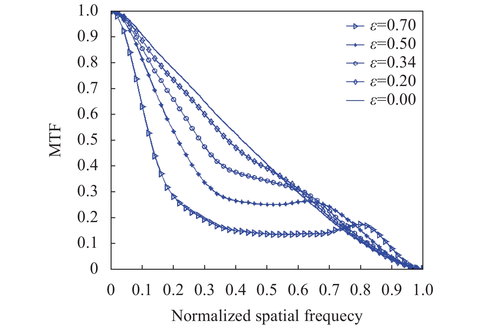
    Fig. 1. Diffraction-limited MTFs of catadioptric lens under different line obscuration ratio ε
    Raytrace diagram (a) and MTFs (b) of the two-mirror Ritchey Chretien system
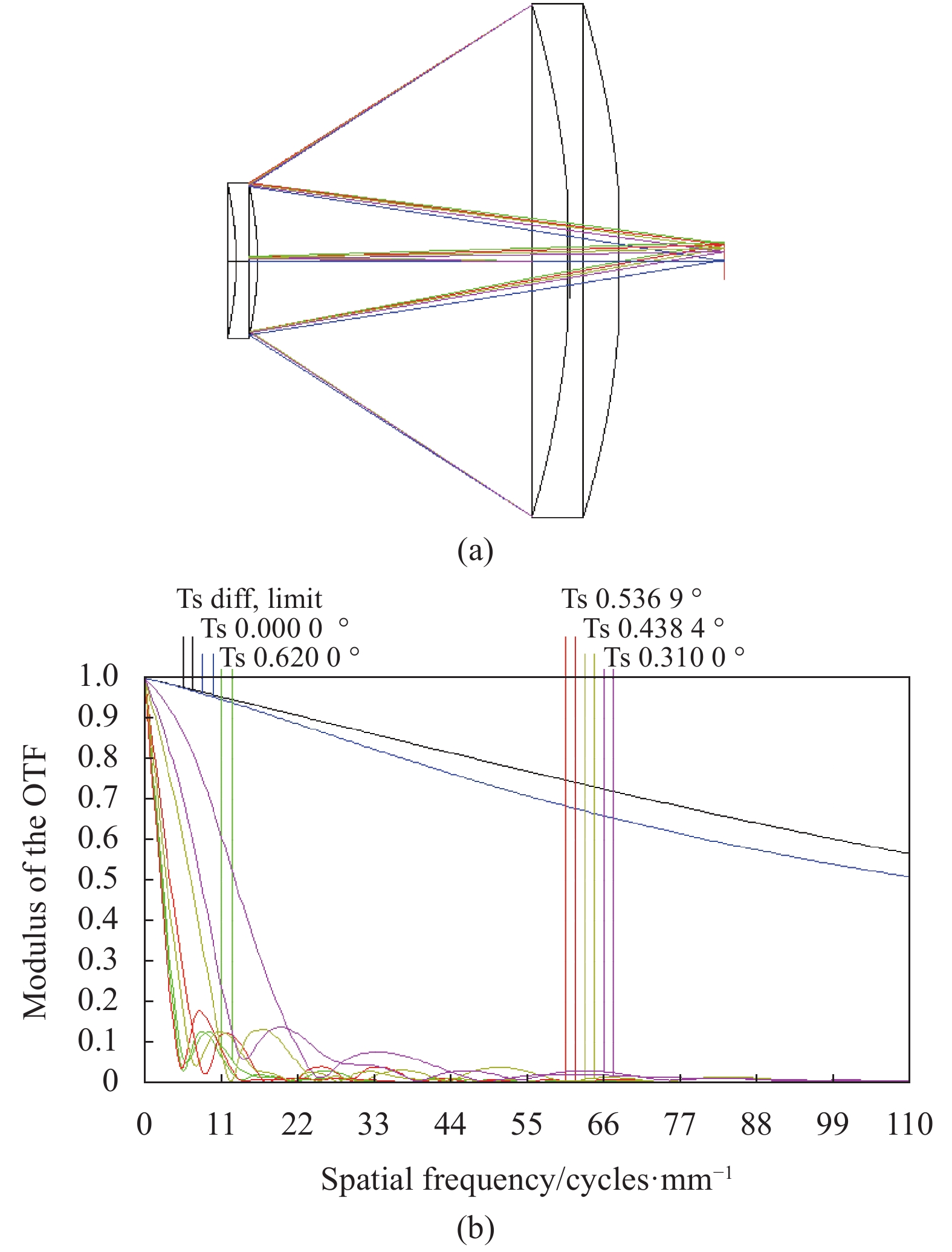
    Fig. 2. Raytrace diagram (a) and MTFs (b) of the two-mirror Ritchey Chretien system
    [in Chinese]
    Fig. 3. [in Chinese]
    Two-dimension (a) and three-dimension (b) raytrace diagrams of the MW infrared/visible shrink-beam system
    Fig. 3. Two-dimension (a) and three-dimension (b) raytrace diagrams of the MW infrared/visible shrink-beam system
    MTFs of MW infrared/visible shrink-beam system (with full field angle of ±0.62°)
    Fig. 4. MTFs of MW infrared/visible shrink-beam system (with full field angle of ±0.62°)
    [in Chinese]
    Fig. 5. [in Chinese]
    Raytrace diagram and position of the MW infrared/visible rear image system
    Fig. 5. Raytrace diagram and position of the MW infrared/visible rear image system
    MTFs of the MW infrared/visible rear image system
    Fig. 6. MTFs of the MW infrared/visible rear image system
    Three-dimension (a) and two-dimension (b) raytrace diagrams of the compact MW infrared/visible imaging detector optical system
    Fig. 7. Three-dimension (a) and two-dimension (b) raytrace diagrams of the compact MW infrared/visible imaging detector optical system
    MTFs of the MW infrared/visible imaging detector on staring image mode (with full field angle of 0.77°×0.62°)
    Fig. 8. MTFs of the MW infrared/visible imaging detector on staring image mode (with full field angle of 0.77°×0.62°)
    MTFs of the MW infrared/visible imaging detector on whisking broom mode (with full field angle of 0.77°×0.62°)
    Fig. 9. MTFs of the MW infrared/visible imaging detector on whisking broom mode (with full field angle of 0.77°×0.62°)
    Focusing components and effects for the MW infrared image sub-system with thermal adaptability
    Fig. 10. Focusing components and effects for the MW infrared image sub-system with thermal adaptability
    NITDs of surfaces and total NITD of the MW infrared image sub-system
    Fig. 11. NITDs of surfaces and total NITD of the MW infrared image sub-system
    PST of the MW infrared image sub-system at different incident angles
    Fig. 12. PST of the MW infrared image sub-system at different incident angles
    Visible optical detectorMedium-wave infrared optical detector
    Waveband/μm0.6-0.93.6-4.9
    Pupil aperture/mm360360
    Full field of view angle/(°)0.77×0.6150.77×0.615
    Focal length/mm1752±21430±1
    Pixel size/mm0.00460.015
    Image resolution≥(5120×4096)≥(1280×1024)
    Table 1. Optical system parameters of visible and medium-wave infrared imaging detector
    Nominal value−30 ℃−10 ℃0 ℃10 ℃30 ℃50 ℃65 ℃In vacuum
    Air interval value20.1620.1520.1620.1620.1620.1620.1720.1720.16
    Adjustment00.640.380.270.15−0.15−0.38−0.55−0.21
    ΔMTF00.1230.1400.1080.0370.0360.1550.1290.057
    Table 2. Adjustment and ΔMTF@33.34 lp/mm of focusing components at different temperatures and in vacuum
    Component listProcess requirementsAssembly requirements
    NΔNEdge thickness differenceRefractive indexDecenterLinear tiltSpace
    Primary mirror20.5--0.005-0.005
    Secondary mirror20.5--0.0050.0050.02
    Prism50.50.011×10−30.10.050.02
    Lenses50.50.011×10−30.015/0.010.020.02
    Table 3. Process and assembly requirements for MW infrared image sub-system
    Angle of viewNominal MTF valuesCalculated MTF values
    MTFTMTFSMTFTMTFS
    0.0°, 0.0°0.2700.2700.2390.249
    0.27°, 0.0°0.2630.2270.2330.196
    0.385°, 0.0°0.2550.1880.2230.152
    0.0°,0.22°0.2420.2660.2080.245
    0.27°, 0.22°0.2320.2210.1980.191
    0.385°,0.22°0.2250.1850.1910.150
    0.0°,3.1°0.2140.2610.1750.237
    0.27°, 3.1°0.2050.2150.1690.186
    0.385°, 3.1°0.2020.1830.1690.152
    Table 4. Tolerance sensitivity analysis result of the MW infrared image sub-system
    Bo Liu, Aimin Liu, Qiaoling Li, Laiyun Xie. Optical design and analysis of compact visible and medium-wave infrared whisking broom imaging system[J]. Infrared and Laser Engineering, 2021, 50(8): 20200517
    Download Citation