• Acta Optica Sinica
  • Vol. 44, Issue 8, 0814001 (2024)
Xiangyu Li1, Yanhong Wang2、*, Jingzhi Wu2, and Peng Zhang1
Author Affiliations
  • 1School of Instrument and Electronics, North University of China, Taiyuan 030051, Shanxi , China
  • 2School of Information and Communication Engineering, North University of China, Taiyuan 030051, Shanxi , China
  • show less
    DOI: 10.3788/AOS231818 Cite this Article Set citation alerts
    Xiangyu Li, Yanhong Wang, Jingzhi Wu, Peng Zhang. Optical Trapping Enhancement Design Based on Plasmon Vortex Field[J]. Acta Optica Sinica, 2024, 44(8): 0814001 Copy Citation Text show less
    Coaxial structure. (a) Overall diagram; (b) longitudinal cross-section of the structure
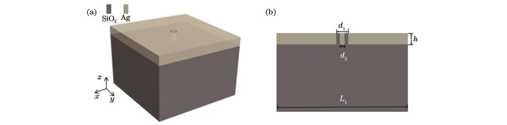
    Fig. 1. Coaxial structure. (a) Overall diagram; (b) longitudinal cross-section of the structure
    Normalized transmission characteristics at different heights
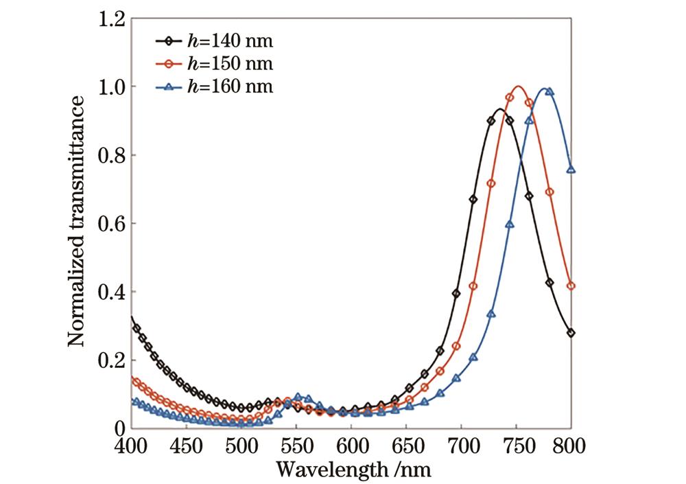
    Fig. 2. Normalized transmission characteristics at different heights
    Electric field distribution in the coaxial aperture x-z plane corresponds to transmission peak value. (a) Electric field at 540 nm peak; (b) electric field at 750 nm peak
    Fig. 3. Electric field distribution in the coaxial aperture x-z plane corresponds to transmission peak value. (a) Electric field at 540 nm peak; (b) electric field at 750 nm peak
    x-y plane electric field distribution of coaxial structure under different light source modes. (a) Horizontal linear polarized light; (b) vertical polarized light; (c) circularly polarized light (levorotation); (d) circularly polarized light (dextrorotation)
    Fig. 4. x-y plane electric field distribution of coaxial structure under different light source modes. (a) Horizontal linear polarized light; (b) vertical polarized light; (c) circularly polarized light (levorotation); (d) circularly polarized light (dextrorotation)
    Ez component of horizontal line polarized light. (a) Electric field distribution; (b) Poynting vector
    Fig. 5. Ez component of horizontal line polarized light. (a) Electric field distribution; (b) Poynting vector
    Ez component electric field distribution and Poynting vector diagrams under circularly polarized light (dextrorotation). (a)(d) Coaxial aperture of 25 nm; (b)(e) coaxial aperture of 40 nm; (c)(f) coaxial aperture of 55 nm
    Fig. 6. Ez component electric field distribution and Poynting vector diagrams under circularly polarized light (dextrorotation). (a)(d) Coaxial aperture of 25 nm; (b)(e) coaxial aperture of 40 nm; (c)(f) coaxial aperture of 55 nm
    Distribution of light trapping force and potential well depth in x-y plane under different light source modes. (a) Light trapping force; (b) potential well depth
    Fig. 7. Distribution of light trapping force and potential well depth in x-y plane under different light source modes. (a) Light trapping force; (b) potential well depth
    Distribution of light trapping force and potential well depth in y-z plane under different light source modes. (a) Light trapping force; (b) potential well depth
    Fig. 8. Distribution of light trapping force and potential well depth in y-z plane under different light source modes. (a) Light trapping force; (b) potential well depth
    Xiangyu Li, Yanhong Wang, Jingzhi Wu, Peng Zhang. Optical Trapping Enhancement Design Based on Plasmon Vortex Field[J]. Acta Optica Sinica, 2024, 44(8): 0814001
    Download Citation