
Zhihai Liu, Tong Wang, Yaxun Zhang, Xiaoyun Tang, Peikun Liu, Yu Zhang, Xinghua Yang, Jianzhong Zhang, Jun Yang, Libo Yuan, "Single fiber dual-functionality optical tweezers based on graded-index multimode fiber," Chin. Opt. Lett. 16, 053501 (2018)
- Chinese Optics Letters
- Vol. 16, Issue 5, 053501 (2018)
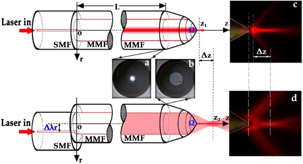
Fig. 1. Schematic of the graded-index MMF optical tweezers probe structure. a, image of the MMF profile light field in the core when Δ λ r = 0 Δ λ r = 10 μm Δ λ r = 0 Δ λ r = 10 μm
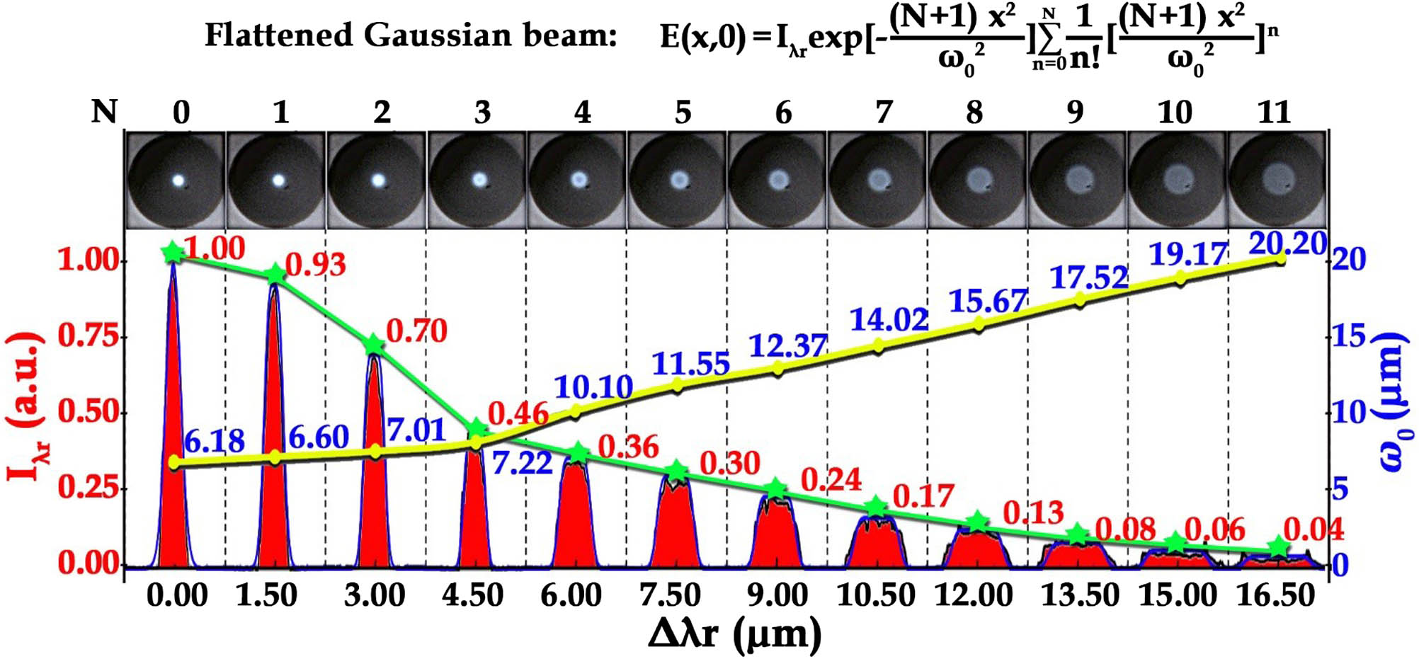
Fig. 2. Relationship between Δ λ r I λ r Δ λ r ω 0 Δ λ r I λ r ω 0
Fig. 3. Schematic of the fiber probes with different shapes fabricated by different methods. a, the awl shape fiber probe tip fabricated by using the heating-drawing method; b, the axial force produced by the awl shape fiber tip; c, the ellipsoid shape fiber probe tip fabricated by using the two-step method; d, the axial force produced by the ellipsoid shape fiber tip; e, the tapered shape fiber probe tip fabricated by using the grinding–polishing method; f, the axial force produced by tapered shape fiber tip.
Fig. 4. a, simulated results of the axial optical trapping force introduced by the graded-index MMF probes with the grinding angles of θ 1 = 20 ° θ 2 = 30 ° θ 3 = 56 ° Δ λ r z d
Fig. 5. Experimental setup structure diagram of the graded-index MMF optical tweezers system. a, the schematic showing the fiber grinding and polishing configuration.
Fig. 6. Visualization 1. a, relationship between d z Δ λ r Ω


Set citation alerts for the article
Please enter your email address

© Copyright 2018-2021 | Chinese Laser Press. All Rights Reserved 沪ICP备15018463号-20