We propose and demonstrate single fiber dual-functionality optical tweezers based on a graded-index multimode fiber. By using the multi-angle fiber grinding and polishing technology, we fabricate the multimode fiber tip to be a special tapered shape, contributing to focus the outgoing beam with a large intensity gradient for the first functionality—three-dimensional contactless trapping of a microparticle. By adjusting the radial direction offset between the lead-in single mode fiber and the graded-index multimode fiber, we perform the second functionality—axial shift of the trapped microparticle with respect to the fiber tip without need of moving the fiber probe itself. It is convenient for practical applications. The theoretical and experimental results about the relationship between the radial offset and the equilibrium positions of the microparticle have the good consistency. Tailoring the trap and axial shift of the microparticle based on the graded-index multimode fiber provides convenient avenues for fiber optical tweezers applied in practical researches.
Since the optical tweezers were first proposed by Ashkin[1], they have been gradually applied to the biological and medical researching fields[2–9], such as cells, viruses, and bacteria manipulations. Traditional lens-based optical tweezers normally employ a high numerical aperture (NA) lens to the focus beam for a microparticles trap. Although successfully used in many experiments, the traditional optical tweezers have some intrinsic limitations resulting from their bulkiness and lack of flexibility. The realization of optical trapping based on optical fibers allows a miniaturized, versatile, and handy tool to be obtained. Originally, the fiber optical tweezers have to employ multiple fibers to perform a single optical trap[10–16]. Thus, the multi-fiber optical tweezers need beam-alignment configurations to ensure the beams from different fibers converge. The single fiber optical tweezers[17,18] may perform the optical trapping without utilizing of the beam-alignment configurations, having the advantages of low-cost and easy to manipulate. Recently, the single fiber multi-functionality optical tweezers are developed[19–22]. On the basis of microstructured multicore fibers, the single fiber multi-functionality optical tweezers perform multiple functionalities, such as trapping, rotating[19], stretching, trapping position shifting[23], and others. However, due to the expensive price and scarce output of the microstructured multicore fiber, the applications of microstructured multicore fiber optical tweezers are narrow. In summary, it is difficult for single fiber optical tweezers to achieve multiple functionalities based on a single core, single-mode fiber (SMF) unless it combines with other mechanics, such as the thermal effect[24]. In fact, besides the SMF, the multimode fiber (MMF) also can be used to fabricate the optical tweezers[25–29]. Gong demonstrates a three-dimensional contacting optical trap[25] and a two-dimensional non-contact optical trap[27] based on a graded-index MMF. To obtain a focusing laser beam and large gradient force, they employed the graded-index MMF with exact control length, due to the self-focusing effect (the beam that propagates in the graded-index MMF will be periodic convergence and divergence). The length of the graded-index MMF is limited to about a few hundred microns, which is inconvenient for practical applications.
In this Letter, on basis of the graded-index MMF, we propose and demonstrate the MMF optical tweezers, which may perform stable three-dimensional, non-contact optical trapping of a yeast cell by using a tapered shape fiber tip produced with the multi-angle fiber grinding and polishing method. The special tapered shape of the fiber tip ensures the long trapping distance and non-invasive optical manipulation. In addition, the MMF optical tweezers can also drive the axial directional shift of the trapped microparticle with respect to the fiber tip by adjusting the radial directional offset between the lead-in SMF and the graded-index MMF. Being different from the reports based on graded-index MMF introduced by Gong[25,26], we employ the radial directional offset adjustment method in the optical tweezers, which eliminates the requirement for the precise control of the MMF length, contributing to the convenience for practical applications. The excitation and utilization of the dual-functionality MMF optical tweezers constitute a new development for single fiber optical tweezers and provides the possibility of much more practical applications in the biomedical research fields.
The laser beam performs a stable intensity distribution after it propagates in a graded-index MMF for a long distance () due to the coupling of multiple mode groups[30]. When the radial directional offset between the lead-in SMF and the graded-index MMF increases, the higher order mode groups will be excited, and the spot size of the beam propagating in the core will be amplified[30]. The beams with different spot sizes converge on different positions when they pass through the fiber tip, whose shape is modified to be a special tapered shape, having the potential to perform non-contact, multi-position optical trapping. The special tapered shape fiber tip can be regarded as an optical lens with special focusing property. The beam with different mode field diameters will focus on different positions due to the special tapered shape of the tip. Figure 1 provides the configuration of the graded-index MMF optical tweezers.
Sign up for Chinese Optics Letters TOC. Get the latest issue of Chinese Optics Letters delivered right to you!Sign up now
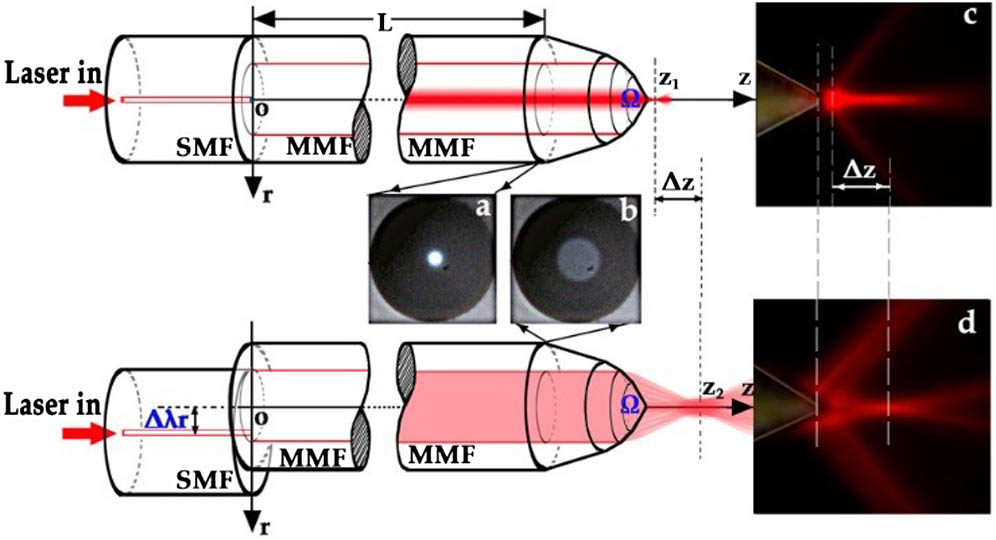
Figure 1.Schematic of the graded-index MMF optical tweezers probe structure. a, image of the MMF profile light field in the core when ; b, image of the MMF profile light field in the core when μ; c, the lateral view image of the focused output light field from the MMF when , here we employ the dye Eosin Y in the solution. We use the green light source of 532 nm to illuminate and a red light filter to observe. d, the lateral view image of the focused output light field from the MMF when μ. The images are all taken by CCD.
We employ a lead-in SMF (Clear-Lite980 Photonic Fibers, OFS) and a graded-index MMF (GI 62.5/125-27/250, YOFC) to fabricate the dual-functionality fiber-based optical tweezers probe. The cladding diameter of the SMF is 125 μm, and the core diameter is 4.6 μm. The NA of the SMF is 0.14. The cladding diameter of the MMF is 125 μm, and the core diameter is 62.5 μm. The NA of the MMF is 0.275. The refractive index profile of the graded-index MMF can be expressed as where is the maximum of the refractive index at , is the core radius, is the factor that determines the index profile. The refractive index difference between the core and the cladding is , where , , and . The length of the MMF is . We grind and polish the MMF tip to be a special tapered shape with multiple angles , and . The solid angle of the fiber tip is named . The radial offset , which is defined as the radial direction offset between center of the lead-in SMF and the MMF (see Fig. 1), determines the spot size of the outgoing beam. The larger is, the larger the spot size of the beam is. When changes from zero to , the amplitudes of the beam decrease gradually, and the diameters of the spots increase gradually. Thus, the focus position of the outgoing beam shifts from to (see Fig. 1), when changes from zero to .
Different excites different mode groups: when , the lower order mode groups are excited, the laser power concentrates in center of the MMF core, and the spot size is small; when increases gradually, the higher order mode groups are excited, and the spot size extends. In the experiment, when increases from 0 to 16.5 μm with the step of 1.5 μm, the spot size of the outgoing beam increases from 6.18 to 20.20 μm, and the normalized peak power of the outgoing beam decreases from 1 to 0.04; the beam total power decreases from 1 to 0.96 (see Fig. 2), and is defined as the beam radius at which the field intensity values fall to of the maximum values. The green stars connected by green lines show the measured intensity, and the solid circles connected by yellow lines show the measured spot radius. It indicates that we may focus the outgoing beam on different positions and trap the microparticle on different positions if we modify the MMF probe tip to be a suitable shape. The spot size of the outgoing beam is unrelated to the length of the MMF, which overcomes the limitation of the precise control of the MMF length, promoting the convenience of the MMF optical tweezers for practical applications.
Figure 2.Relationship between and the intensity of the outgoing beam and the relationship between the and the spot size of the outgoing beam. The range of the is from 0 to 16.5 μm, the range of the is from 0 to 1, and the range of is from 6.18 to 20.20 μm.
Besides the radial offset , the fiber tip shape of the graded-index MMF also determines the optical trapping force magnitudes and the trapping positions. The shape of the fiber tip acts as a lens, thus modifying propagation and intensity distribution of the outgoing beam in the external medium. Normally, we divide the fiber tip shape into three categories, which are awl shape, ellipsoid shape, and tapered shape (see Fig. 3). By using the common fiber “fused biconical taper” method, the fiber tip is normally processed to be the awl shape (see Fig. 3a). The awl shape fiber tip adsorbs particles being close to the fiber tip (see Fig. 3b[16]), which may cause some damages on cell membranes, resulting in the awl shape fiber tip being unsuitable for biological applications. In order to perform the non-contact optical trap, a “two-step” method[22] is used to fabricate the ellipsoid shape fiber (see Fig. 3c). Although it can achieve the non-contact trap, the trapping position is still close to the fiber end (see Fig. 3d). When we employ the ellipsoid shape fiber tip to trap large microparticles ( of the microparticle), it still performs the contacting trap. By using the multi-angle fiber “grinding and polishing” method, we may fabricate the fiber probe tip to be a special tapered shape (see Fig. 3e). The tapered shape can be regarded as multiple truncated cones arranged in layers. It is convenient and feasible to modulate light field distribution of the outgoing beam by grinding and polishing the fiber tip step by step with multiple grinding angles. Thus, we may perform the non-contact trap and ensure that the trapping position is far away from the fiber tip (see Fig. 3f). For the MMF optical tweezers probe, we employ the multi-angle grinding and polishing technology to fabricate the tapered shape fiber tip.
Figure 3.Schematic of the fiber probes with different shapes fabricated by different methods. a, the awl shape fiber probe tip fabricated by using the heating-drawing method; b, the axial force produced by the awl shape fiber tip; c, the ellipsoid shape fiber probe tip fabricated by using the two-step method; d, the axial force produced by the ellipsoid shape fiber tip; e, the tapered shape fiber probe tip fabricated by using the grinding–polishing method; f, the axial force produced by tapered shape fiber tip.
Both and determine the optical trapping state of the MMF probe. We investigate the optical trapping force introduced by the fiber tip with a solid angle of with diversification of in range of 0 to 10 μm. On the basis of COMSOL Multiphysics software, we simulate the optical trapping force generated from the MMF probe exerting on the yeast cells. Other simulated conditions include the laser source wavelength of 0.98 μm. The incident laser power is 2 mW. The average radius of the yeast cell is 3 μm. The refractive index of the background media is 1.33, and the refractive index of the yeast cell is 1.4[31].
Figure 4a provides the calculated results of the axial trapping force introduced by the graded-index MMF probe with a solid angle of (including the grinding angles , , and , see Fig. 4b). is the distance between the center of the microparticle and the fiber tip. The values of the axial directional optical trapping force decrease along with the increment of . The stable trap position introduced by the MMF probe shifts from 7.2 to 15.92 μm when increases from 0 to 10 μm. Compared with the axial direction shifting range introduced by SMF based on the mode complexing technology[22], the shifting range introduced by the MMF is longer, expanding the adjustable range of the trapped microparticle along the axial direction.
Figure 4.a, simulated results of the axial optical trapping force introduced by the graded-index MMF probes with the grinding angles of , , and and different . b, the schematic diagram of the grinding angles. c, the schematic diagram to define .
Figure 5 shows the experimental setup of the graded-index MMF optical tweezers system. A 1:99 fiber coupler is employed to launch and monitor the laser power in the lead-in the SMF in real-time. A 980 nm laser-pumping source with the power adjusting range of 0–300 mW is employed for optical trapping. Two three-dimensional adjustable frames are employed to mount the fibers and change the radial directional offset between the lead-in SMF and the MMF. The MMF probe is fixed on the three-dimensional micromanipulator, whose resolution is 62.5 nm/step. A 40 times objective (the NA is 0.25, and the focal depth is 8 mm) and a CCD (the resolution is 30 frame/s) are used for observing the performance of the MMF probe. All devices are mounted on the air-bearing table to ensure the stability in the experiment. The yeast cells in the aqueous solution are used as the manipulating objects. The average diameter of the yeast cells is 6 μm, and the refractive index of the yeast cell is 1.4. A multi-angle fiber grinding–polishing technology is employed to fabricate the fiber tapered tip. According to Fig. 5a, two direct current motors are employed to drive the grinding plate and rotate the fiber at the same time. The grinding angle of the fiber probe tip depends on the angle between the fiber rotation axis and the grinding plane.
Figure 5.Experimental setup structure diagram of the graded-index MMF optical tweezers system. a, the schematic showing the fiber grinding and polishing configuration.
In the experiment, we set , and the laser power to be 15.92 mW; by using the graded-index MMF probe with , we achieve the stable non-contact trap of the yeast cell. We move the trapped yeast cell in the three-dimensional space by moving the fiber probe in the three-dimensional space (see Visualization 1). We increase from 0 to 10 μm with the step of 2 μm. The trapped yeast cell moves from μ to μ (see Figs. 6a and 6b). We can also achieve the trapped yeast cell to move from μ back to μ by changing from 10 to 0 μm. Figure 6 shows that the theoretical and experimental results about the relationship between the radial offset and the equilibrium positions of the microparticle have a good consistency. But when exceeds 10 μm, the MMF probe will lose the capturing ability. The reason is that the optical power density decreases as increases. The laser power cannot be focused strongly to generate sufficient optical gradient force to trap the yeast.
Figure 6.Visualization 1. a, relationship between and when the laser power is 15.92 mW. b, images of the graded-index MMF probe with the of 56° trapping and changing the position of the yeast cell.
We also fabricate an MMF probe based on a step-index MMF (SI105/125-22/250) with the same method. The core diameter of the MMF is 105 μm, and the NA is 0.22. The spot size of the outgoing beam does not change when the radial offset between the lead-in SMF and the MMF changes. The distribution of the laser power is random, resulting in the instability of the laser power distribution. Therefore, the step-index MMFs are not suitable for fiber-based optical tweezers.
In conclusion, we propose and demonstrate the fiber optical tweezers based on a graded-index MMF, which performs a stable three-dimensional, non-contact, position-adjustable optical trap. The experimental results show that, when the solid angle of the MMF probe is 56°, the MMF optical tweezers can three-dimensionally trap a yeast cell without contact and perform the axial reciprocating motion in the range of 0–8.6 μm by changing the radial offset between the lead-in SMF and MMF from 0 to 10 μm. Due to the simple fabricating method, low testing cost, and two manipulating functionalities, the MMF optical tweezers have the potential to be applied to diverse research fields, such as biomedicine, micromanipulation, chemistry, and others.