Author Affiliations
1Photonic Device Physics Laboratory, Institute of Physics and Applied Physics, Yonsei University, Seoul 03722, South Korea2Department of Physics and Energy Systems Research, Ajou University, Suwon 16499, South Koreashow less
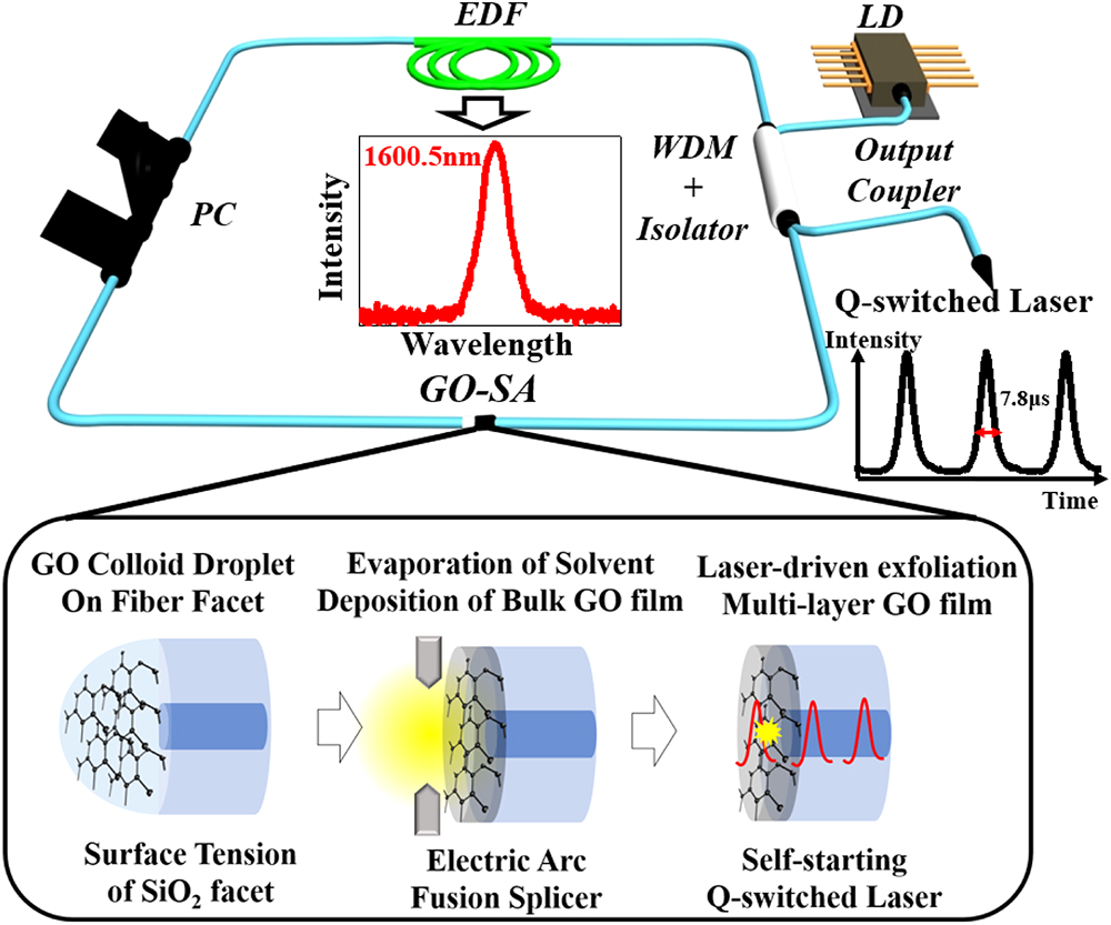
Fig. 1. Schematic diagram of the proposed deposition process and Q switching of an Er-doped fiber laser using a graphene oxide saturable absorber. The inset shows the three steps in the proposed GO deposition by using the electric arc and self-starting Q-switched laser pulses. (LD, pump laser diode at λ=980 nm; PC, polarization controller; EDF, Er-doped fiber; WDM, 980 nm/1550 nm wavelength-division multiplexer; GO-SA, graphene oxide saturable absorber.)
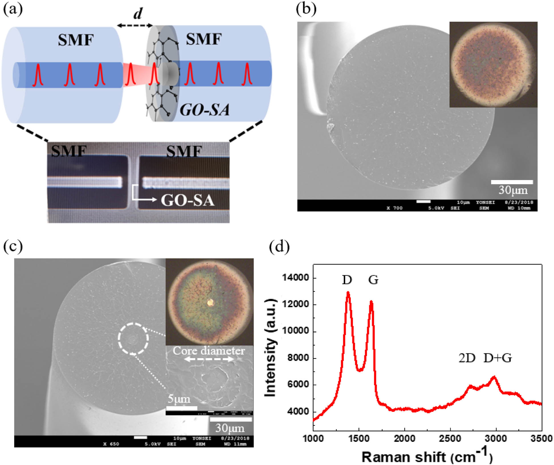
Fig. 2. (a) Configuration of the fabricated all-fiber GO-SA. The inset picture was taken from the fusion splicer. The gap between two fiber facets, d, was optimized to be ∼8 μm. (b) Scanning electron microscope (SEM) image of the GO bulk film on the fiber facet deposited by the electric arc. Inset is its optical microscopic image. (c) SEM images of the GO multi-layer film on the fiber facet formed by laser-driven self-exfoliation. The blown SEM image clearly shows a layered structure on the fiber core. The inset is its optical microscopic image, where the light was guided through the core with a significantly thinner GO multi-layer film. (d) Micro Raman spectrum of the deposited GO film on the fiber core after the laser-driven self-exfoliation. (SMF, single mode fiber; GO-SA, graphene oxide saturable absorber.)
Fig. 3. (a) Linear transmission spectrum of GO bulk film on a silica substrate. (b) The measurement setup for the nonlinear transmission of the GO-SA formed by the laser-driven self-exfoliation process. (c) Nonlinear transmission of the GO-SA as a function of the input laser intensity. (GO-SA, graphene oxide saturable absorber; VOA, variable optical attenuator; PC, polarization controller.)
Fig. 4. Schematic diagram of Q switching experimental setup using the all-fiber GO-SA. The output of the laser was monitored in the wavelength spectral domain, RF domain, and time domain. (GO-SA, graphene oxide multi-layer film saturable absorber; LD, laser diode; EDF, erbium-doped fiber; PD, photodetector; PC, polarization controller; hybrid component, an integrated wavelength-division multiplexer and isolator; OSA, optical spectrum analyzer.)
Fig. 5. Lasing characteristics for the bulk GO film device in the ring laser cavity: (a) optical spectra, (b) RF spectra and the oscilloscope trace in the inset. Here the pump laser power was ∼149 mW.
Fig. 6. Lasing characteristics of the Q-switched EDFL using the multi-layer GO-SA. (a) Optical spectrum (the inset shows the peak wavelength of the output laser for CW, unstable pulsing, and stable Q-switched pulsing); (b) RF spectrum; (c) oscilloscope trace of the pulse train. (d) Pulse repetition rate and pulse width as functions of the pump power; (e) output power and pulse energy as functions of the pump power. (f) Duty cycle and peak power as functions of the pump power.
Fig. 7. (a) Schematic diagram of transmission measurements for the fabricated multi-layer GO-SA with the gap of ∼8 μm. (b) Fabry–Perot filter simulation (black line), experimental measurements (blue line), and the laser output (red line).
Material | Types of SA | Deposition Method | Wavelength(nm) | Pulse Width (μs) | Max. Peak Power (mW) | Pulse Energy (nJ) | Repetition Rate (kHz) | Ref. | GO | SPFa | Spray method | 1558 | 2.12 | – | – | 8.96 | [22] | GO | PCFb | Solution filled inside the PCF | 1553.42–1561.67 | – | 0.167 | 8.98 | 16 | [23] | GO | End face | Polymer-based thin film | 1558–1570 | 6.6–13.7 | – | 19.2–61.3 | 22–61 | [24] | GO | End face | Optical deposition | 1531.6 | 20.44–61.2 | 9.3 | 46.6–145.0 | 21.5–68.7 | [25] | GO | End face | Laser induced self-exfoliation | 1600.5 | 7.8–24.0 | 15.4 | 47.6–128.1 | 6.3–17.8 | This work |
|
Table 1. -Switched EDFLs Based on Graphene Oxide Saturable Absorbers
Material | Types of SA | Method | Wavelength (nm) | Min. Pulse Width (μs) | Max. Pulse Energy (nJ) | Max. Repetition Rate (kHz) | Max. Output Power (mW) | Ref. | ZnO | End face | Polymer-based thin film | 1536–1586 | 4.5 | 39.9 | 28.9 | 1.2 | [46] | | End face | Mechanical exfoliation | 1533–1573 | 2.2 | 13.5 | 52 | 0.7 | [47] | | End face | Polymer-based thin film | 1534–1570 | 2.7 | – | 22.2 | 0.087 | [48] | Ag | End face | Polymer-based thin film | 1552.9–1580.2 | 11.9 | – | 10.5 | 0.044 | [49] | GO | End face | Laser induced self-exfoliation | 1600.5 | 7.8 | 128.1 | 17.8 | 2.3 | This work |
|
Table 2. Performance Comparison of the Present Result to Recent -Switched EDFLs Incorporating Other Materials in the L-Band