
Rongquan Chen, Qing Wang. Propagation Properties of Off-Axis Double Vortex Single Beam in Nonlocal Media[J]. Laser & Optoelectronics Progress, 2021, 58(21): 2119001
- Laser & Optoelectronics Progress
- Vol. 58, Issue 21, 2119001 (2021)
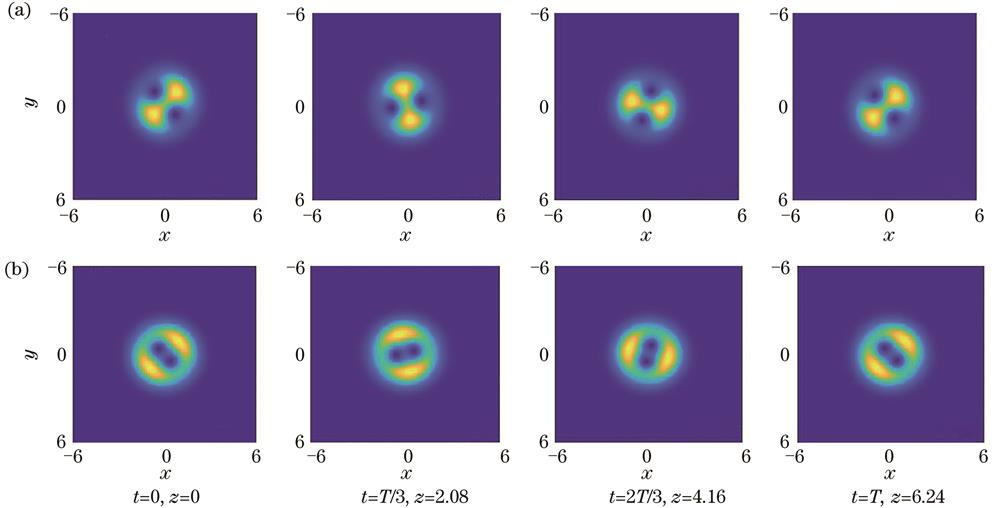
Fig. 1. Intensity distribution of symmetric vortex beam under different conditions. (a) a=-c=-0.7, b=-d=-0.7, and p=17506; (b) a=-c=-0.4, b=-d=-0.4, and p=17506
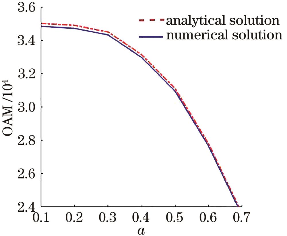
Fig. 2. Comparison of numerical and analytical solutions for orbital angular momentum
Fig. 3. Light intensity distribution of oblique transmission under different conditions. (a) m=n=1, a =b=-0.7, c=d=0.3, and p=17506; (b) direction of circulation of vortex is negative, m=n=1, a=b=-0.7, c=d=0.3, and p=17506; (c) m=1, n=2, a=-c=-0.7, b=-d=-0.7, and p=18004
Fig. 4. Three-dimensional propagation of light beams. (a) m=n=1, a=-c=-0.7, b=-d=-0.7, and p=17506; (b) m=n=1, a=b=-0.7, c=d=0.3, and p=17506; (c) direction of circulation of vortex is negative, m=n=1, a=b=-0.7, b=-d=0.3, and p=17506; (d) m=1, n=2 ,a=-c=-0.7, b=d=-0.7, and p=18004
Fig. 5. Beam performance results. (a) m=n=1, a=-c =-0.1, b=-d=-0.1, and p=17450; (b) m=n=2, a=-c=-0.1, b=-d=-0.1, and p=18815; (c) vortex reverse, m=n=2 ,a=-c=-0.2, b=-d=-0.2, and p=18846
Fig. 6. Beam width under different conditions. (a) m=n=1,a=-c=-0.1,b=-d=-0.1,p=17450; (b) m=n=2,a=-c=-0.1,b=-d=-0.1,p=18815; (c) m=n=2,a=-c=-0.2,b=-d=-0.2,p=18846
Fig. 7. Relationship among angular momentum, critical power and different parameters. (a) Relationship among angular momentum, critical power, and position of vortex; (b) relationship between angular momentum and m; (c) relationship between critical power and m

Set citation alerts for the article
Please enter your email address
© Copyright 2018-2021 | Chinese Laser Press. All Rights Reserved 沪ICP备15018463号-20