• Acta Optica Sinica
  • Vol. 43, Issue 9, 0914001 (2023)
Chunyang Wang1、2, Wen Shuai2, Bo Xiao3、*, Siling Huang4, and Dasen Wang4
Author Affiliations
  • 1Xi'an Key Laboratory of Active Photoelectric Imaging Detection Technology, Xi'an Technological University, Xi'an 710021, Shaanxi , China
  • 2School of Electronic and Information Engineering, Changchun University of Science and Technology, Changchun 130022, Jilin , China
  • 3School of Optoelectronic Engineering, Xi'an Technological University, Xi'an 710021, Shaanxi , China
  • 4Ningbo Branch of Chinese Academy of Ordnance Science, Ningbo 315103, Zhejiang , China
  • show less
    DOI: 10.3788/AOS221863 Cite this Article Set citation alerts
    Chunyang Wang, Wen Shuai, Bo Xiao, Siling Huang, Dasen Wang. Uniformity Removal Based on Processing Prediction Model of Ring-Pendulum Double-Sided Polishing Method[J]. Acta Optica Sinica, 2023, 43(9): 0914001 Copy Citation Text show less
    Structure diagram of ring pendulum double-sided rapid polishing machine
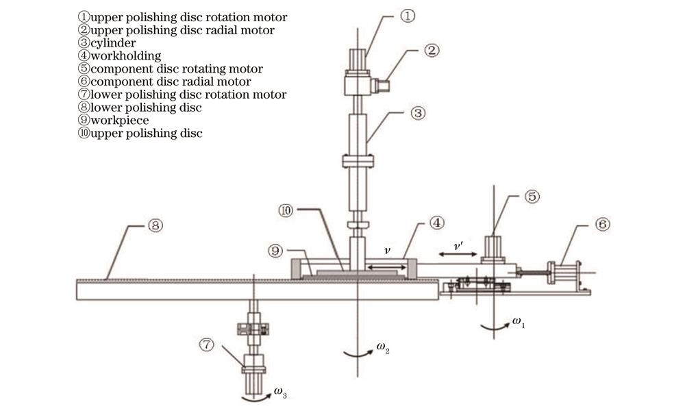
    Fig. 1. Structure diagram of ring pendulum double-sided rapid polishing machine
    ANSYS static pressure modeling simulation
    Fig. 2. ANSYS static pressure modeling simulation
    Schematic diagram of kinematic analysis of abrasive particles
    Fig. 3. Schematic diagram of kinematic analysis of abrasive particles
    Inspection results of components. (a) Comparison of actual machining and simulation results of 1# workpiece; (b) comparison of actual machining and simulation results of 2# workpiece; (c) comparison of actual machining and simulation results of 3# workpiece
    Fig. 4. Inspection results of components. (a) Comparison of actual machining and simulation results of 1# workpiece; (b) comparison of actual machining and simulation results of 2# workpiece; (c) comparison of actual machining and simulation results of 3# workpiece
    Distributions of removal amount from upper and lower surfaces of workpiece. (a) Distribution of removal amount on upper surface; (b) distribution of removal amount on lower surface
    Fig. 5. Distributions of removal amount from upper and lower surfaces of workpiece. (a) Distribution of removal amount on upper surface; (b) distribution of removal amount on lower surface
    Average removal amount of upper and lower surfaces of workpiece under different groups of parameters
    Fig. 6. Average removal amount of upper and lower surfaces of workpiece under different groups of parameters
    Mean square error of removal amount of upper and lower surfaces under different groups of parameters
    Fig. 7. Mean square error of removal amount of upper and lower surfaces under different groups of parameters
    Trajectory distributions of polishing abrasive particles under different center eccentricity. (a) Center eccentricity is 0 mm; (b) center eccentricity is 15 mm; (c) center eccentricity is 30 mm; (d) center eccentricity is 45 mm; (e) center eccentricity is 60 mm
    Fig. 8. Trajectory distributions of polishing abrasive particles under different center eccentricity. (a) Center eccentricity is 0 mm; (b) center eccentricity is 15 mm; (c) center eccentricity is 30 mm; (d) center eccentricity is 45 mm; (e) center eccentricity is 60 mm
    Trajectory distributions of polishing abrasive particles under different radial swing distances. (a) Radial swing distance is 0 mm; (b) radial swing distance is 15 mm; (c) radial swing distance is 30 mm; (d) radial swing distance is 45 mm; (e) radial swing distance is 60 mm
    Fig. 9. Trajectory distributions of polishing abrasive particles under different radial swing distances. (a) Radial swing distance is 0 mm; (b) radial swing distance is 15 mm; (c) radial swing distance is 30 mm; (d) radial swing distance is 45 mm; (e) radial swing distance is 60 mm
    Trajectory distributions of polishing abrasive particles under different radial swing speed. (a) Radial swing speed is 1 mm/s; (b) radial swing speed is 3 mm/s; (c) radial swing speed is 5 mm/s; (d) radial swing speed is 7 mm/s; (e) radial swing speed is 9 mm/s
    Fig. 10. Trajectory distributions of polishing abrasive particles under different radial swing speed. (a) Radial swing speed is 1 mm/s; (b) radial swing speed is 3 mm/s; (c) radial swing speed is 5 mm/s; (d) radial swing speed is 7 mm/s; (e) radial swing speed is 9 mm/s
    Initial surfaces of different workpieces. (a) Initial surface of 1# workpiece; (b) initial surface of 2# workpiece
    Fig. 11. Initial surfaces of different workpieces. (a) Initial surface of 1# workpiece; (b) initial surface of 2# workpiece
    Inspection results of experimental components. (a) Machined surface of 1# workpiece; (b) machined surface of 2# workpiece
    Fig. 12. Inspection results of experimental components. (a) Machined surface of 1# workpiece; (b) machined surface of 2# workpiece
    Workpiece numberCenter eccentricity distance of upper disk /mmRadial swing distance of upper disk /mmRadial swing velocity of upper disk /(mm·s-1
    1#40101
    2#20303
    3#30206
    Table 1. Configuration of simulation machining parameters
    Workpiece numberCenter eccentricity distance of upper disk /mmRadial swing distance of upper disk /mmRadial swing velocity of upper disk /(mm·s-1
    1#15157
    2#30601
    Table 2. Configuration of experimental processing parameters
    Chunyang Wang, Wen Shuai, Bo Xiao, Siling Huang, Dasen Wang. Uniformity Removal Based on Processing Prediction Model of Ring-Pendulum Double-Sided Polishing Method[J]. Acta Optica Sinica, 2023, 43(9): 0914001
    Download Citation