• Infrared and Laser Engineering
  • Vol. 51, Issue 4, 20210317 (2022)
Hongnan Zhao1, Wensong Jiang1, Li Yang1, Zai Luo1, and Hongyang Li2
Author Affiliations
  • 1College of Metrology and Measurement Engineering, China Jiliang University, Hangzhou 310018, China
  • 2Science and Technology on Space Physics Laboratory, China Academy of Launch Vehicle Technology, Beijing 100076, China
  • show less
    DOI: 10.3788/IRLA20210317 Cite this Article
    Hongnan Zhao, Wensong Jiang, Li Yang, Zai Luo, Hongyang Li. Correction method for edge deviation of line laser sensor[J]. Infrared and Laser Engineering, 2022, 51(4): 20210317 Copy Citation Text show less
    Schematic diagram of line laser sensor
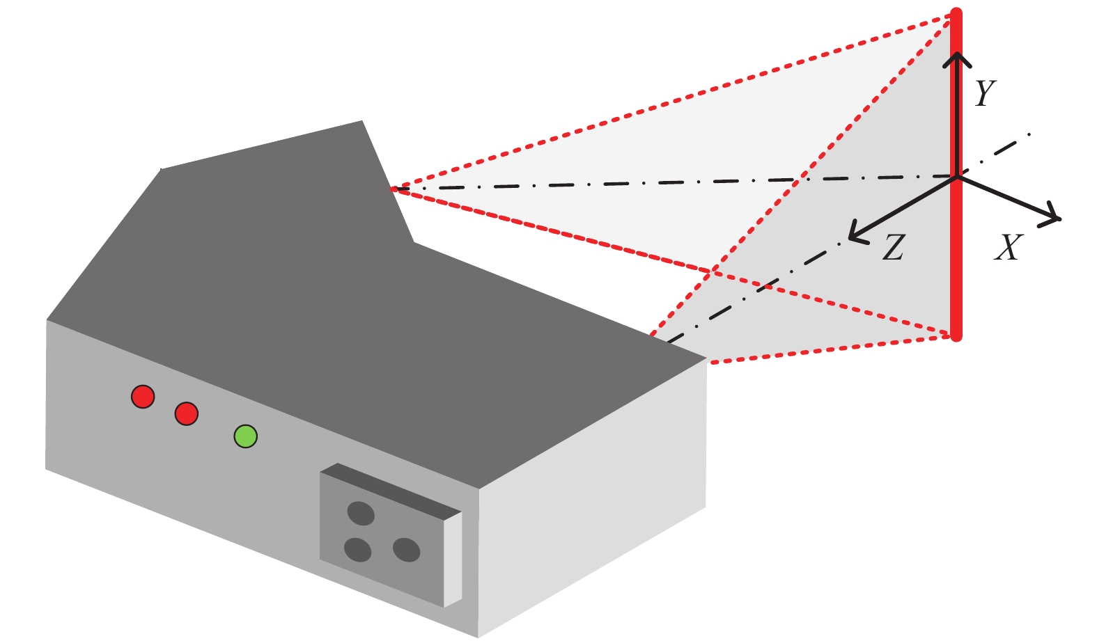
    Fig. 1. Schematic diagram of line laser sensor
    (a) Line laser contour scanning;(b) Edge enlargement
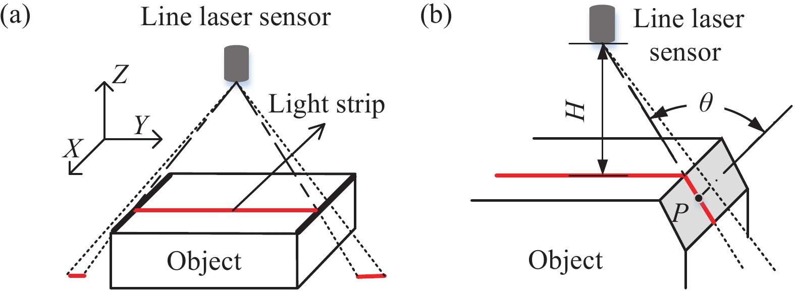
    Fig. 2. (a) Line laser contour scanning;(b) Edge enlargement
    Image processing error
    Fig. 3. Image processing error
    (a) Vertical side noise;(b) Edge enlargement
    Fig. 4. (a) Vertical side noise;(b) Edge enlargement
    Filtering process of vertical side noise
    Fig. 5. Filtering process of vertical side noise
    Illustration of interpolation compensation
    Fig. 6. Illustration of interpolation compensation
    (a) Experiment platform; (b) Scanned object
    Fig. 7. (a) Experiment platform; (b) Scanned object
    (a) Noise removal effect;(b) Edge enlargement
    Fig. 8. (a) Noise removal effect;(b) Edge enlargement
    Design of dimensional measurement scheme
    Fig. 9. Design of dimensional measurement scheme
    (a) First sampling; (b) Mth sample
    Fig. 10. (a) First sampling; (b) Mth sample
    (a) Dimension measurement of 20 mm gauge block; (b) Dimen-sion measurement of 40 mm gauge block; (c) Dimension measurement of 60 mm gauge block
    Fig. 11. (a) Dimension measurement of 20 mm gauge block; (b) Dimen-sion measurement of 40 mm gauge block; (c) Dimension measurement of 60 mm gauge block
    Dimension measurement error before and after compensation
    Fig. 12. Dimension measurement error before and after compensation
    ModuleIndicators and parameters
    Standard gauge blockLimit deviation: ±0.6 μm
    Edge feature: Chamfer
    Line laser sensorY axis accuracy: 0.045 mm
    Z axis range: −60-40 mm
    High-precision rotary tableResolution: 0.02°
    Positioning accuracy: 0.05°
    Table 1. Parameters of equipment
    Size of gauge blockNo compensationya=0.078 mm, K=2 ya=0.039 mm, K=5
    LmeasΔLmeasΔLmeasΔ
    2019.590.4319.900.1019.960.04
    4039.5739.9139.98
    6059.5559.8939.95
    Table 2. Dimension measurement results before and after error compensation (Unit: mm)
    Hongnan Zhao, Wensong Jiang, Li Yang, Zai Luo, Hongyang Li. Correction method for edge deviation of line laser sensor[J]. Infrared and Laser Engineering, 2022, 51(4): 20210317
    Download Citation