• Acta Optica Sinica
  • Vol. 41, Issue 5, 0522003 (2021)
Zhanyu Liu1、2, Peipei Wang2、**, Zhiliang Jin2, Haiyang Wang2, and Daxi Xiong2、*
Author Affiliations
  • 1School of Opto-Electronic Engineering, Changchun University of Science and Technology, Changchun, Jilin 130022, China
  • 2Center of Light and Health, Suzhou Institute of Biomedical Engineering and Technology, Chinese Academy of Sciences, Suzhou, Jiangsu 215163, China
  • show less
    DOI: 10.3788/AOS202141.0522003 Cite this Article Set citation alerts
    Zhanyu Liu, Peipei Wang, Zhiliang Jin, Haiyang Wang, Daxi Xiong. Free-Form Lens Design for LED Fishing Lamp with Stable Illumination[J]. Acta Optica Sinica, 2021, 41(5): 0522003 Copy Citation Text show less
    Illumination range of LED fishing lamps
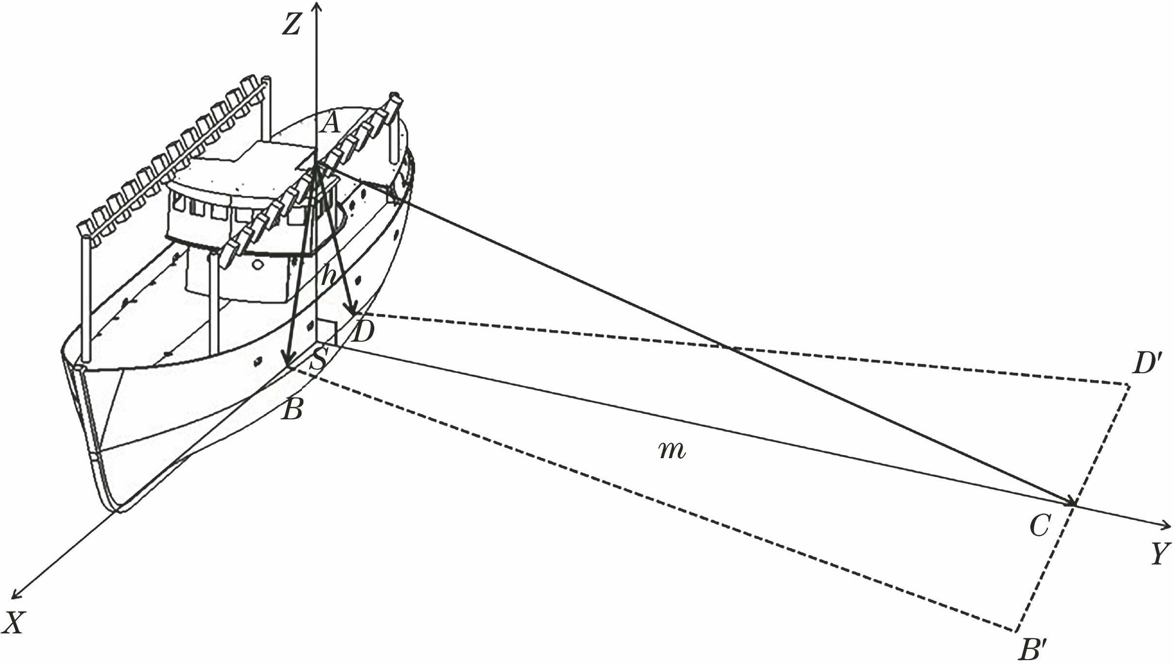
    Fig. 1. Illumination range of LED fishing lamps
    Relationship between the divergent angle of 110° and the effective irradiation angle of 90° of LED fishing lamp under different rolling angles. (a) Boat tilting to the left; (b) boat not rolling; (c) boat tilting to the right
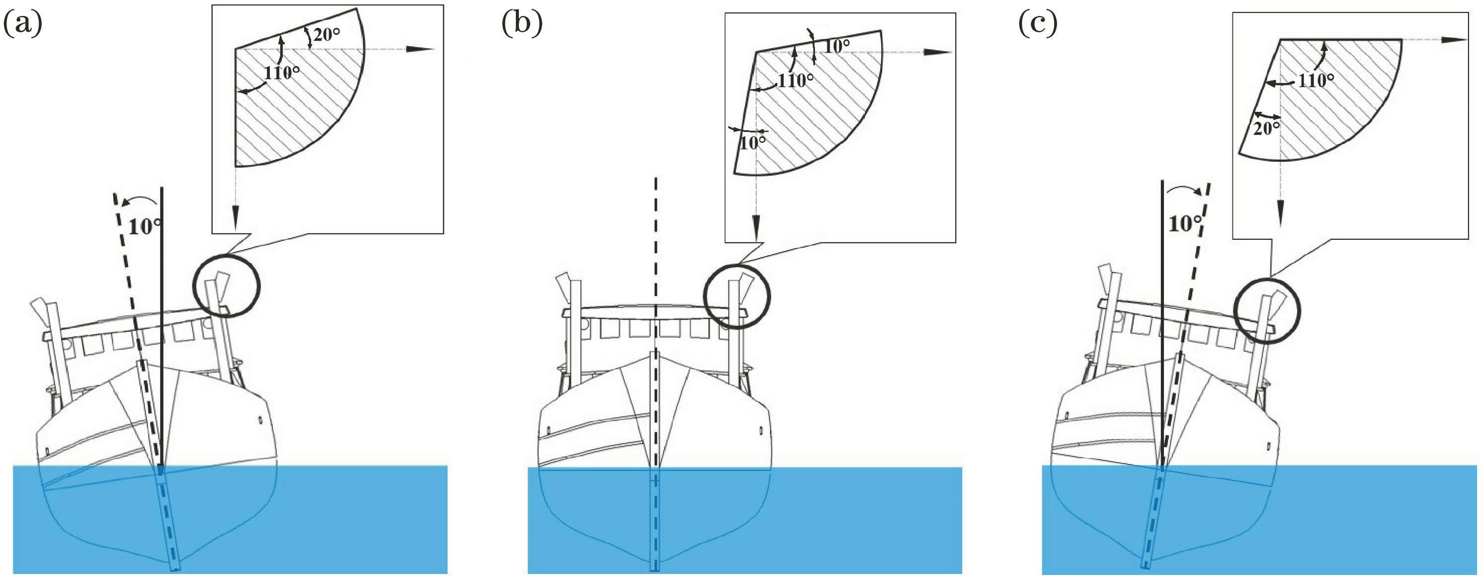
    Fig. 2. Relationship between the divergent angle of 110° and the effective irradiation angle of 90° of LED fishing lamp under different rolling angles. (a) Boat tilting to the left; (b) boat not rolling; (c) boat tilting to the right
    Divergence angle of LED fishing lamp. (a) Fan-shaped divergence angle is 110° on the Y-Z cross-section; (b) small divergence angle on the X-Y cross-section
    Fig. 3. Divergence angle of LED fishing lamp. (a) Fan-shaped divergence angle is 110° on the Y-Z cross-section; (b) small divergence angle on the X-Y cross-section
    Package of LED chips. (a) 3D model of LED module; (b) distribution of LED chips
    Fig. 4. Package of LED chips. (a) 3D model of LED module; (b) distribution of LED chips
    Schematic of the cross-section of optical system and light path
    Fig. 5. Schematic of the cross-section of optical system and light path
    Ray tracing on the first surface and second surface of Y-Z cross-section
    Fig. 6. Ray tracing on the first surface and second surface of Y-Z cross-section
    Ray tracing on the first surface and second surface of X-Y cross-section
    Fig. 7. Ray tracing on the first surface and second surface of X-Y cross-section
    Structure of the free-form lens. (a) 3D model of the lens; (b) Y-Z cross-section of the lens; (c) fabricated free-form lens sample
    Fig. 8. Structure of the free-form lens. (a) 3D model of the lens; (b) Y-Z cross-section of the lens; (c) fabricated free-form lens sample
    Light intensity distribution of LED fishing lamps in Y-Z plane and X-Y plane
    Fig. 9. Light intensity distribution of LED fishing lamps in Y-Z plane and X-Y plane
    Illuminance distribution on the target surface under different illumination angles. (a) 0°; (b) -10°; (c) -5°; (d) 5°; (e) 10°
    Fig. 10. Illuminance distribution on the target surface under different illumination angles. (a) 0°; (b) -10°; (c) -5°; (d) 5°; (e) 10°
    Experiment measurement. (a) Field illumination effect; (b) location of the test points
    Fig. 11. Experiment measurement. (a) Field illumination effect; (b) location of the test points
    Simulated and experimental relative illumination distributions on the target plane along Y-axis direction at different illumination angles. (a) 0°; (b) -10°; (c) -5°; (d) 5°; (e) 10°
    Fig. 12. Simulated and experimental relative illumination distributions on the target plane along Y-axis direction at different illumination angles. (a) 0°; (b) -10°; (c) -5°; (d) 5°; (e) 10°
    Pictures of fishing lamp. (a) Improved LED fishing lamp; (b) ordinary LED fishing lamp[10]; (c) metal halide lamp
    Fig. 13. Pictures of fishing lamp. (a) Improved LED fishing lamp; (b) ordinary LED fishing lamp[10]; (c) metal halide lamp
    Flux distribution curves of fishing lamp. (a) Improved LED fishing lamp; (b) ordinary LED fishing lamp[10]; (c) metal halide lamp
    Fig. 14. Flux distribution curves of fishing lamp. (a) Improved LED fishing lamp; (b) ordinary LED fishing lamp[10]; (c) metal halide lamp
    Relative illuminance distribution of fishing lamp. (a) Improved LED fishing lamp; (b) ordinary LED fishing lamp[10]; (c) metal halide lamp
    Fig. 15. Relative illuminance distribution of fishing lamp. (a) Improved LED fishing lamp; (b) ordinary LED fishing lamp[10]; (c) metal halide lamp
    ParameterSimulation resultsExperimental results
    Illumination angle /(°)-10-5510-10-5510
    NCC /%99.9299.9699.8998.5099.9699.9599.5399.66
    RMSE /%1.440.981.635.562.170.884.603.53
    Table 1. NCC and RMSE of simulation results and experimental results
    ParameterImproved LED fishing lampOrdinary LED fishing lampMetal halide lamp
    Illumination angle /(°)-10-5510-10-5510-10-5510
    NCC /%99.9299.9699.8998.5070.3488.8587.1462.2296.4197.6197.6296.04
    RMSE /%1.440.981.635.5620.4111.6410.8217.3713.126.776.2712.05
    Table 2. Illumination stability of three fishing lamps
    Zhanyu Liu, Peipei Wang, Zhiliang Jin, Haiyang Wang, Daxi Xiong. Free-Form Lens Design for LED Fishing Lamp with Stable Illumination[J]. Acta Optica Sinica, 2021, 41(5): 0522003
    Download Citation