• Photonics Research
  • Vol. 5, Issue 6, 695 (2017)
Min Tang, Yong-Zhen Huang*, Yue-De Yang, Hai-Zhong Weng, and Zhi-Xiong Xiao
Author Affiliations
  • State Key Laboratory on Integrated Optoelectronics, Institute of Semiconductors, University of Chinese Academy of Sciences, Chinese Academy of Sciences, Beijing 100083, China
  • show less
    DOI: 10.1364/PRJ.5.000695 Cite this Article Set citation alerts
    Min Tang, Yong-Zhen Huang, Yue-De Yang, Hai-Zhong Weng, Zhi-Xiong Xiao. Variable-curvature microresonators for dual-wavelength lasing[J]. Photonics Research, 2017, 5(6): 695 Copy Citation Text show less
    Schematic diagram of a 2D VCM. The curvature is linearly changed as the boundary starting from zero curvature points to the neighboring maximum-curvature points.
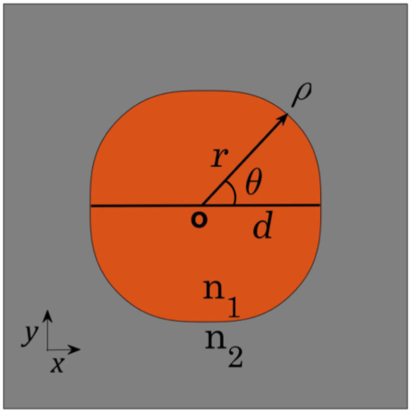
    Fig. 1. Schematic diagram of a 2D VCM. The curvature is linearly changed as the boundary starting from zero curvature points to the neighboring maximum-curvature points.
    (a) Mode intensity spectrum and mode field patterns |Hz| of the (b) circular-like mode, (c) fundamental four-bounce mode, (d) first-order four-bounce mode, and (e) high-order hybrid mode.
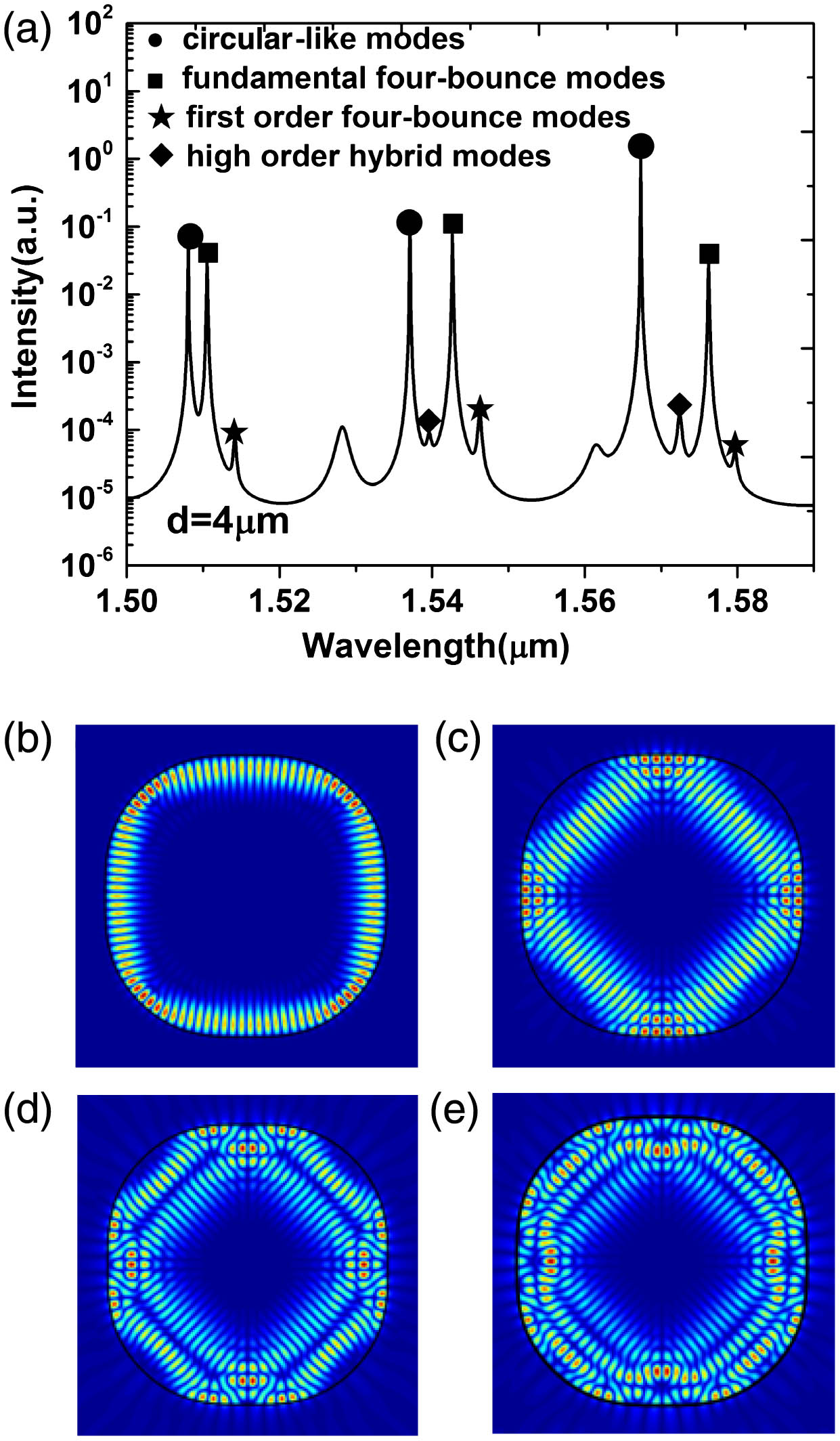
    Fig. 2. (a) Mode intensity spectrum and mode field patterns |Hz| of the (b) circular-like mode, (c) fundamental four-bounce mode, (d) first-order four-bounce mode, and (e) high-order hybrid mode.
    Q factors and wavelengths for deformed resonator from VCM to (a) microcircular resonator and (b) microsquare resonator.
    Fig. 3. Q factors and wavelengths for deformed resonator from VCM to (a) microcircular resonator and (b) microsquare resonator.
    (a) Poincaré surface of sections (SOSs) of VCM; inset shows ray trajectories of two kinds of closed orbits with reflection times of 3000, which are marked by dots of the same color in the phase space. We zoom in on one of the droplets to show the details of the regular regions. (b) Top and droplet centers of the SOS; horizontal and vertical coordinate ranges are expressed on the left and bottom of each graph.
    Fig. 4. (a) Poincaré surface of sections (SOSs) of VCM; inset shows ray trajectories of two kinds of closed orbits with reflection times of 3000, which are marked by dots of the same color in the phase space. We zoom in on one of the droplets to show the details of the regular regions. (b) Top and droplet centers of the SOS; horizontal and vertical coordinate ranges are expressed on the left and bottom of each graph.
    Husimi projections of the (a) circular-like mode and (b) fundamental four-bounce mode. Insets show the field distributions |Hz| of both modes.
    Fig. 5. Husimi projections of the (a) circular-like mode and (b) fundamental four-bounce mode. Insets show the field distributions |Hz| of both modes.
    (a) Wavelengths, Q factors, and (b) frequency differentials of circular-like and fundamental four-bounce modes versus the refractive index change of the dark-colored ring region.
    Fig. 6. (a) Wavelengths, Q factors, and (b) frequency differentials of circular-like and fundamental four-bounce modes versus the refractive index change of the dark-colored ring region.
    Frequencies of the circular-like and fundamental four-bounce modes versus VCM size.
    Fig. 7. Frequencies of the circular-like and fundamental four-bounce modes versus VCM size.
    (a) Q factors of dual mode versus waveguide rotating angles and field distributions of |Hz| for the circular-like modes with rotating angles of (b) 0° and (c) 27°, and for the fundamental four-bounce modes with rotating angles of (d) 27° and (e) 45°.
    Fig. 8. (a) Q factors of dual mode versus waveguide rotating angles and field distributions of |Hz| for the circular-like modes with rotating angles of (b) 0° and (c) 27°, and for the fundamental four-bounce modes with rotating angles of (d) 27° and (e) 45°.
    ModeWavelength (μm)Q Factor
    Circular-like modes1.50724.34×105
    1.53721.68×105
    1.56644.51×104
    Four-bounce modes1.50961.51×104
    1.54281.51×104
    1.57531.25×104
    First-order four-bounce modes1.51334.13×103
    1.54533.27×103
    1.57872.81×103
    High-order hybrid modes1.50832.42×103
    1.53972.61×103
    1.57262.76×103
    Table 1. Wavelengths and Q Factors for Symmetric TE Modes in VCM with d=4  μm
    r/0.5a/d(μm)45678
    Circular resonator G10/G000.620.650.640.630.64
    Square resonator G10/G001.001.001.001.010.72
    VCM Gsc/Gcc0.52\0.510.440.58
    Table 2. Ratios of Cross-Saturation Coefficient to Self-Saturation Coefficient
    Min Tang, Yong-Zhen Huang, Yue-De Yang, Hai-Zhong Weng, Zhi-Xiong Xiao. Variable-curvature microresonators for dual-wavelength lasing[J]. Photonics Research, 2017, 5(6): 695
    Download Citation