• Chinese Optics Letters
  • Vol. 17, Issue 12, 120604 (2019)
Zhike Zhang1、2, Jinye Li3, Zeping Zhao3, Jianguo Liu3、*, and Xingjun Wang1、2、**
Author Affiliations
  • 1State Key Laboratory of Advanced Optical Communication Systems and Networks, School of Electronics Engineering and Computer Science, Peking University, Beijing 100871, China
  • 2Frontiers Science Center for Nano-optoelectronics, Peking University, Beijing 100871, China
  • 3State Key Laboratory on Integrated Optoelectronics, Institute of Semiconductors, Chinese Academy of Sciences, Beijing 100083, China
  • show less
    DOI: 10.3788/COL201917.120604 Cite this Article Set citation alerts
    Zhike Zhang, Jinye Li, Zeping Zhao, Jianguo Liu, Xingjun Wang. Package-level passive equalization technology enabling DML-based 112 Gbps/λ PAM4 transmission[J]. Chinese Optics Letters, 2019, 17(12): 120604 Copy Citation Text show less
    (a) TX equalization, (b) RX equalization, (c) proposed package-level equalization.
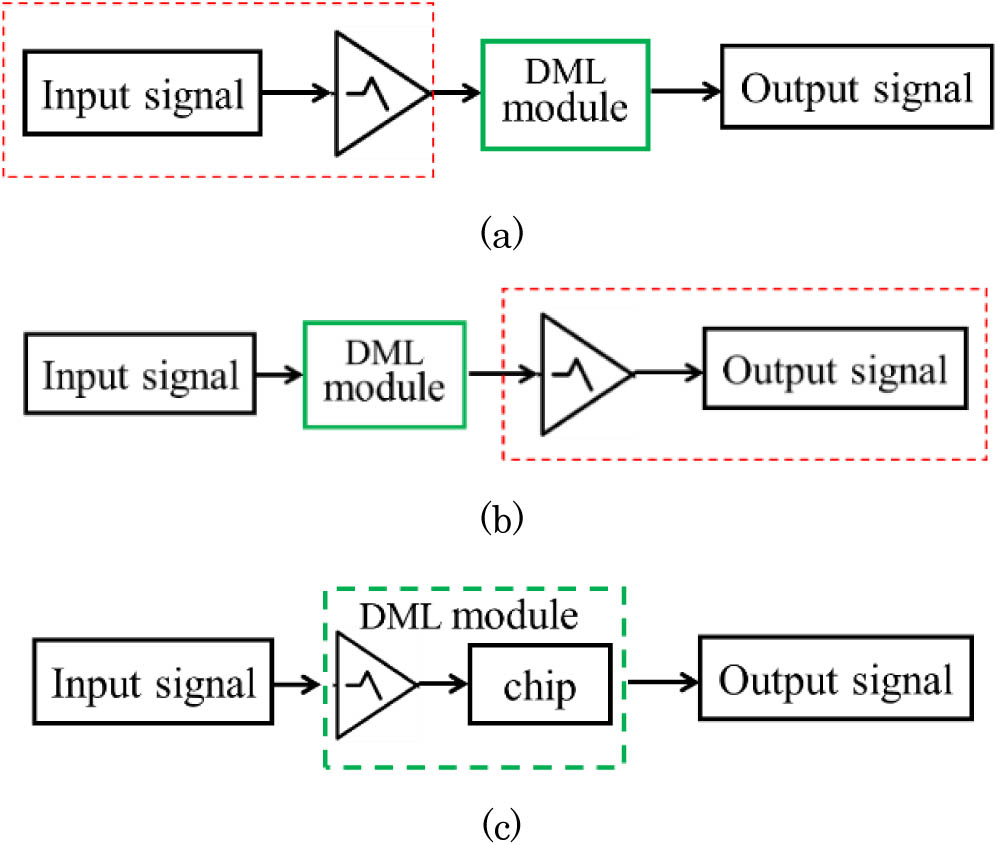
    Fig. 1. (a) TX equalization, (b) RX equalization, (c) proposed package-level equalization.
    Circuit model for the high-frequency package network of a DML. The S parameters of the package assembly are measured using the vector network analyzer, and the s2p file is embedded in the circuit. The inset shows the bond wire between the chip pad and the package assembly.
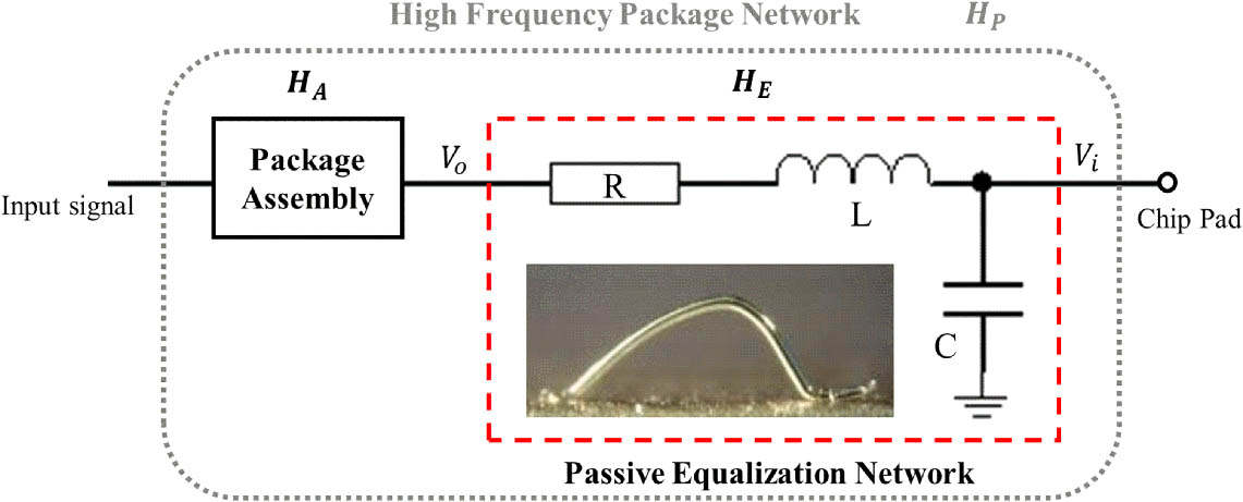
    Fig. 2. Circuit model for the high-frequency package network of a DML. The S parameters of the package assembly are measured using the vector network analyzer, and the s2p file is embedded in the circuit. The inset shows the bond wire between the chip pad and the package assembly.
    Contour maps of gain strength versus inductance and capacitance at frequencies of 10, 15, 20, 25, 30, and 35 GHz.
    Fig. 3. Contour maps of gain strength versus inductance and capacitance at frequencies of 10, 15, 20, 25, 30, and 35 GHz.
    Measured (symbol lines) and simulated (solid lines) transmission parameters of the bond wire used in the DML module. The inset shows the designed measure fixture and the equivalent circuit model used to extract the bonding-induced capacitance.
    Fig. 4. Measured (symbol lines) and simulated (solid lines) transmission parameters of the bond wire used in the DML module. The inset shows the designed measure fixture and the equivalent circuit model used to extract the bonding-induced capacitance.
    Contour map of gain strength versus inductance and capacitance at 22 GHz. The labels show the corresponding gain strengths under the two bond wire length conditions.
    Fig. 5. Contour map of gain strength versus inductance and capacitance at 22 GHz. The labels show the corresponding gain strengths under the two bond wire length conditions.
    Frequency responses of the DML module packaged with and without equalization conditions, measured at a laser current of 90 mA.
    Fig. 6. Frequency responses of the DML module packaged with and without equalization conditions, measured at a laser current of 90 mA.
    Experimental setup for single-wavelength PAM4 signal transmission.
    Fig. 7. Experimental setup for single-wavelength PAM4 signal transmission.
    BER versus the modulation speed with and without equalization cases.
    Fig. 8. BER versus the modulation speed with and without equalization cases.
    BER of 112 Gbps PAM4 signal versus the ROP for the BtB case.
    Fig. 9. BER of 112 Gbps PAM4 signal versus the ROP for the BtB case.
    Zhike Zhang, Jinye Li, Zeping Zhao, Jianguo Liu, Xingjun Wang. Package-level passive equalization technology enabling DML-based 112 Gbps/λ PAM4 transmission[J]. Chinese Optics Letters, 2019, 17(12): 120604
    Download Citation