
Anqi Wang, Zhixin Meng, Yanying Feng. Widely tunable laser frequency offset locking to the atomic resonance line with frequency modulation spectroscopy[J]. Chinese Optics Letters, 2018, 16(5): 050201
- Chinese Optics Letters
- Vol. 16, Issue 5, 050201 (2018)
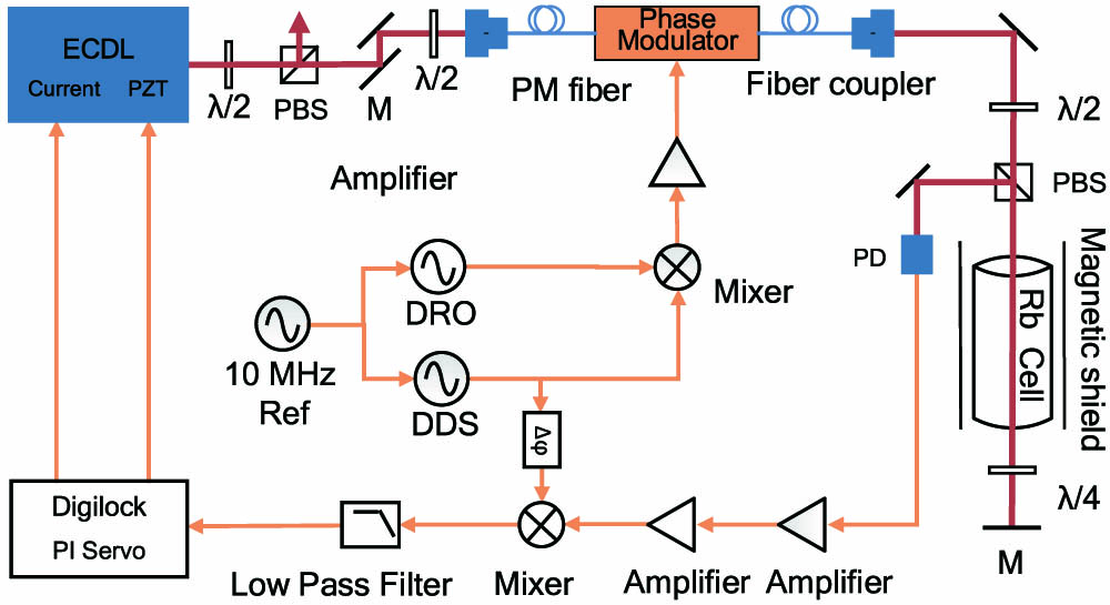
Fig. 1. Schematic of the FMS frequency offset lock. ECDL, external cavity diode laser; PBS, polarization beam splitter; PM fiber, polarization maintaining fiber; FEOM, fiber electro-optic modulator; PD, photodetector; λ / 2 λ / 4
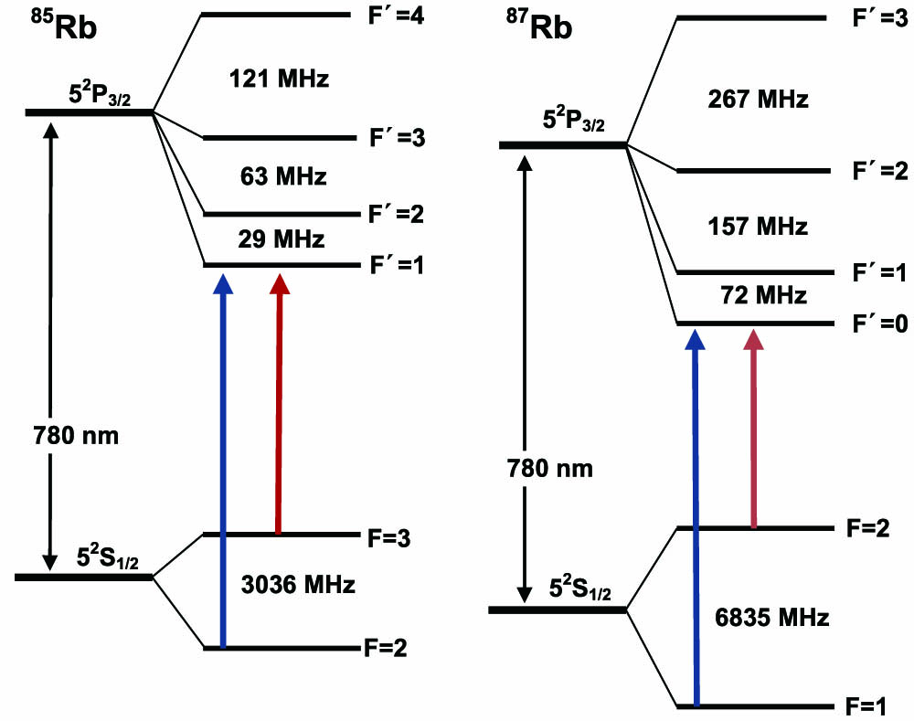
Fig. 2. Energy-level scheme for Rb 85 Rb 87 D 2
Fig. 3. Comparison of (a) referenced SAS signal, (b) FMS signal with the frequency offset of 1 GHz, (c) FMS signal with the frequency offset of 1.2 GHz, (d) FMS signal with the frequency offset of 1.5 GHz, and (e) FMS signal with the frequency offset of 2 GHz.
Fig. 4. Error signals of the offset FMS obtained for different modulation frequencies from the 1st-order sideband with the frequency difference of − 1.5 GHz Rb 87 F = 2 → F ′ = 2 CO 3
Fig. 5. RF beat note power spectrum of two lasers at an offset central frequency of 1.367 GHz. An Agilent E4440A spectrum analyzer is used at a 10 MHz frequency span with a resolution bandwidth (RBW) of 1 kHz. The 3 dB linewidth of the beat note signal is 900 kHz.
Fig. 6. Allan variance of the beat frequency.
Fig. 7. Frequency fluctuations of the frequency offset locked laser for locking on and free running cases.

Set citation alerts for the article
Please enter your email address
© Copyright 2018-2021 | Chinese Laser Press. All Rights Reserved 沪ICP备15018463号-20