Abstract
A simple and robust technique is reported to offset lock a single semiconductor laser to the atom resonance line with a frequency difference easily adjustable from a few tens of megahertz up to tens of gigahertz. The proposed scheme makes use of the frequency modulation spectroscopy by modulating sidebands of a fiber electro-optic modulator output. The short-term performances of a frequency offset locked semiconductor laser are experimentally demonstrated with the Allan variance of around at a 2 s integration time. This method may have many applications, such as in Raman optics for an atom interferometer.The frequency offset locking technique has been a widely used method to stabilize the laser frequencies to a reference with certain frequency differences, which has found applications in many fields, such as precise spectroscopy[1–3], cold atom experiments[4], atom interferometry[5], and atomic or optical clocks[6].
Different techniques have been developed for offset frequencies ranging from a few megahertz (MHz) to tens of gigahertz (GHz) from the absolute reference frequency, like an atom or molecular resonance line. One method is using the master–slave laser scheme, in which a reference laser (master laser) is locked to an atomic resonance line and provides an absolute frequency reference, whereas a probe laser (slave laser) is locked to the master laser based on beat notes between the two lasers. Phase coherent locking can be obtained by using the optical phase-locked loops(OPLLs)[7,8], locking to different longitudinal modes of a tunable Fabry–Perot resonator[9,10] or an optical frequency comb[6], or injection locking by a frequency shift beam with an auxiliary acousto-optical modulator (AOM)[11] or electro-optic modulator (EOM)[12]. In many spectroscopic or atomic experiments, phase coherency is not required, whereas it is sufficient that the slave laser maintains a highly precise frequency offset from the master laser. In these cases, simple locking schemes can be implemented with different methods to generate the error signal, such as by using an electronic delay line[13], a frequency-to-voltage converter[14], a sharp electronic radio frequency (RF) high-pass filter[15], and frequency modulation (FM) on one of the lasers[16]. In these master–slave schemes, an additional reference laser is required and makes the system complicated and not cost-effective when only one laser frequency is needed.
In many applications, it is desirable that a laser is directly frequency offset locked to the absolute reference frequency, like an atom or molecular resonance line, with high bandwidth and low phase noise. Several techniques have been demonstrated with atomic spectroscopy, such as electromagnetically induced transparency (EIT) resonance[17], electromagnetically induced absorption (EIA) resonance[18], buffer gas-induced resonance[19], and the Faraday effect[20]. Another convenient method is using an auxiliary AOM or EOM to shift the frequency and identify the locking point with spectroscopic techniques. The dynamical tuning range is limited by the modulation bandwidth of an AOM (typically less than 50 MHz), and the range of possible offset frequencies is limited by low diffraction efficiency of the device in high-frequency shift. The maximum frequency shift of has been reached in a six-pass configuration of a AOM with the modulation efficiency less than 0.07%[21]. Replacing the AOM with an EOM can extend the dynamical tuning range beyond 100 MHz and the available range of operating frequencies up to tens of gigahertz, like using the waveguide-type EOMs. The carrier or any high-order component generated by the EOM can be locked to a reference atomic transition. Frequency offset locking of 40 GHz to a reference atomic transition has been demonstrated by using the fourth-order sideband generated by an EOM and polarization spectrum frequency stabilization[22]. The use of EOM can solve the conflict between frequency offset capture and efficiency even though it has many useless sidebands, which bring about the problems of phase noise and systematic errors.
Sign up for Chinese Optics Letters TOC. Get the latest issue of Chinese Optics Letters delivered right to you!Sign up now
Among various laser-spectroscopic techniques available to researchers, FM spectroscopy (FMS) is a powerful technique that can achieve a high signal-to-noise ratio with a relatively simple experimental setup. Since Bjorklund’s first demonstrations of the efficiency of FMS with a single-mode continuous-wave dye laser[23], the technique has been widely used as a tunable laser-spectroscopic method in fields such as laser stabilization[24] and trace gas detection[25]. FMS involves phase or frequency modulating the wavelength of a continuous-wave laser with, e.g., an AOM or EOM at a particular frequency and measuring the differential absorption experienced by each sideband as it transverses the saturated medium. As the central wavelength is scanned across the atomic transition, the wavelength modulation is converted into amplitude modulation, giving rise to a modulation in the optical absorption of a sample at the same frequency. Because the signal has been moved to a high frequency via modulation, FMS avoids the typical limitations of absorption measurements, such as laser intensity fluctuations and detector noise, which peak at a DC and fall off roughly as , hence the name noise. Narrow-band demodulation techniques, such as phase-sensitive detection using a lock-in amplifier, then allow the absorption information to be realized at a DC. Using this technique, FM absorption spectroscopy has reached detection sensitivity near to the fundamental quantum noise limit[26].
In this Letter, we demonstrate a new method based on FMS to frequency offset locking a laser directly to the atomic resonance line without any additional reference laser. The offset locking point of the laser frequency referenced to the resonance line can be conveniently and quickly tuned by changing the RF driving a fiber-pigtailed waveguide-type electro-optical phase modulator from a few tens of MHz (limited by the linewidth of the FM spectroscopy) to tens of GHz larger, which mainly depends on the bandwidth of the EOM. The FMS is obtained by modulating the sidebands generated by a fiber EOM (FEOM) with tens of MHz and detecting frequency offset error signals at higher frequencies, which makes the error signal less sensitive to the DC offset drift, compared to the frequency offset locking method based on saturation absorption spectroscopy (SAS)[27] or the polarization spectrum[22,28]. The short-term stability of this scheme is experimentally evaluated by measuring the frequency variation of the beat note between a frequency offset locked semiconductor laser and another independently locked semiconductor laser.
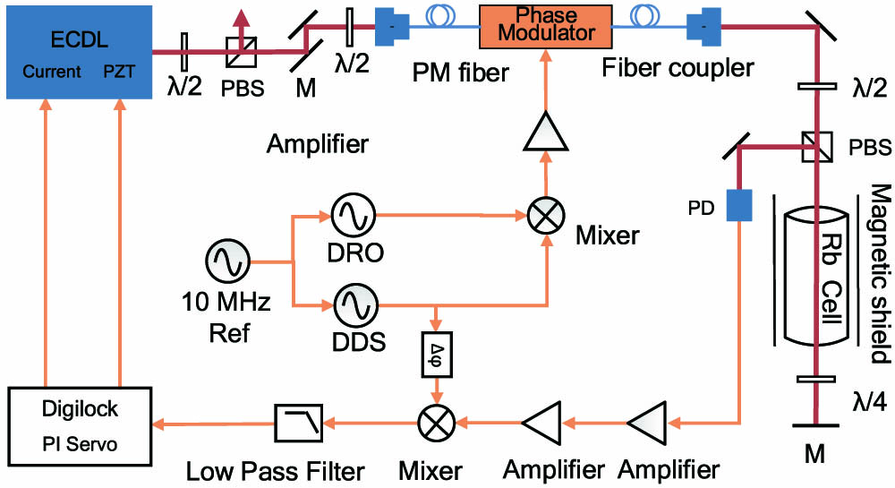
The schematic of our frequency offset-locking system is shown in Fig. 1. The laser is a 780 nm commercial grating extended-cavity diode laser (ECDL, DLpro, Toptica, Germany) with an integrated optical isolator. The typical output power of the ECDL is 80 mW, and the linewidth is 1.5 MHz (1 ms). The laser beam is divided into two beams by a polarizing beam splitter (PBS) for the Raman optics of our atom interferometer and frequency offset locking, respectively. The latter is phase-modulated using a polarization-maintaining FEOM (EOspace, USA), which is driven by a mixed RF signal. The frequency offset signal in the order of GHz is driven by a dielectric resonator oscillator (DRO, NT-LPNFS-09202, Nuotai, China) to generate sidebands in an optical spectrum. The FMS signal is driven by one channel of a dual-channel direct digital synthesizer (DDS, 33500B, Agilent, USA) to modulate the sidebands generated by the FEOM in the order of MHz. These signals are mixed by a frequency mixer (, Mini-Circuits, USA) and power amplified by an RF amplifier (AML12PNA1311, Microsemi, USA) to approximately 30 dBm before input to the FEOM. Both RF signals are synchronized to one external 10 MHz reference oscillator. The power of incident light into the FEOM is 5 mW, and the power of transmitted light is typically 0.8 mW. The low transmission efficiency is due to the low coupling efficiency of the fiber coupler.

Figure 1.Schematic of the FMS frequency offset lock. ECDL, external cavity diode laser; PBS, polarization beam splitter; PM fiber, polarization maintaining fiber; FEOM, fiber electro-optic modulator; PD, photodetector; , half-wave plate; , quarter-wave plate; M, mirror; DDS, direct digital synthesizer.
The output beam of the FEOM with different orders of modulated sidebands passes through a rubidium vapor cell in a simple pump–probe configuration with retro-reflected optics. The probe signal is detected by a fast photodiode (DET210, Thorlabs, USA). After amplification by , the RF heterodyne signal is demodulated on a phase detector (, Mini-Circuits, USA) by mixing with the demodulation signal, which is generated by the other channel of the DDS. A built-in phase shifter within the DDS allows tuning the relative phase difference between the FMS signal and the demodulation signal.
After passing through a low-pass filter and signal amplifier, the error signal is sent to a digital lock-in amplifier (Digilock 110, Toptica, Germany), which allows two field programmable gate array (FPGA)-based proportional–integral–derivative (PID) servos to fast lock the laser current and slow lock the piezo of the external diode laser, respectively. Frequency offset locking is implemented by locking to the zero-cross of the error signal generated by the sideband FMS of the FEOM. Frequency difference is controlled by the RF signal driving the DRO in a range of several GHz.
In the experiments, we set the laser frequency to the “ transition” of the FMS signal generated by the 1st-order sideband of the phase-modulated light, which corresponds to the red detuning from the transition of the line with the DRO driving frequency, and has the maximum relative amplitude and easy-to-distinguish spectrum characteristics. Figure 2 shows the energy level scheme for the and lines. FMS signals with different frequency offsets are shown in Fig. 3. The SAS signal is simultaneously observed as a reference, as shown in Fig. 3(a). Ideally, the output laser frequency can be set at any point in a tens GHz range, which is limited by the bandwidth of the EOM. For the FEOM, we use the tuning range of 20 GHz that can be obtained from to 10 GHz. In the experiments, we set the frequency offset from 0 to 2 GHz due to the bandwidth limitation of the DRO. Compared with the referenced SAS signal, there exist corresponding residual SAS signals induced by carrier frequencies in FMS. But, these carrier-frequency-induced SAS signals are suppressed to a low amplitude level and of absorption characteristics because no FM is applied on carrier frequencies. This lowers the influence of carrier frequency on the FMS signals after the 10 MHz demodulation. However, the frequency offset is still hard to implement in some ranges where the carrier-frequency-induced SAS signals are overlapped with the sideband-frequency-induced FMS signal, as shown in Fig. 3(c).
Figure 2.Energy-level scheme for and line.
Figure 3.Comparison of (a) referenced SAS signal, (b) FMS signal with the frequency offset of 1 GHz, (c) FMS signal with the frequency offset of 1.2 GHz, (d) FMS signal with the frequency offset of 1.5 GHz, and (e) FMS signal with the frequency offset of 2 GHz.
The error signals were optimized by changing the modulation frequency on the sideband of the EOM output and the phase difference between the modulation and demodulation signals with DDS. The offset FMS signal generated by the 1st-order sideband of the EOM output in various modulation frequencies are shown in Fig. 4. Each time the DDS modulation frequency was changed, the phase difference between the modulation and demodulation signals were optimized to get the error signal of the maximum amplitude. In our experiments, the optimum modulation frequency is near 12 MHz, which induces an error signal with a slope sensitivity of and a locking bandwidth of about 20 MHz for the error with frequency offset of . The inset shows the peak-to-peak amplitudes of the error signals with varied DDS modulation frequencies.
Figure 4.Error signals of the offset FMS obtained for different modulation frequencies from the 1st-order sideband with the frequency difference of to the transition. The inset shows the peak-to-peak amplitudes of the error signals with varied DDS modulation frequencies.
The linewidth of the frequency offset locked laser (Fig. 5) was measured by producing the heterodyne beat between two independent laser systems, both of which are the same type of commercial ECDLs (DLpro, Toptica, Germany). The frequency offset locked laser was offset frequency locked to the transition line with the FMS signal generated by the 1st-order sideband of the EOM output. The reference laser was locked to the transition line with the AOM transfer spectroscopy method[29], which has a lower noise level compared with the FMS method by the calculation of error signals. Two ECDLs were locked independently with the separation of 1.367 GHz. The beat was detected with a high-bandwidth photodetector (PD, 3372, New Focus, USA) and analyzed with a spectrum analyzer (E4440A, Agilent, USA). The RF beat spectrum shows a full width at half-maximum (FWHM) linewidth of 900 kHz, which implies individual laser linewidths of less than 900 kHz. The close agreement with a Lorentz fit indicates that the deviations in laser frequency are small compared to the frequencies of modulation[30].
Figure 5.RF beat note power spectrum of two lasers at an offset central frequency of 1.367 GHz. An Agilent E4440A spectrum analyzer is used at a 10 MHz frequency span with a resolution bandwidth (RBW) of 1 kHz. The 3 dB linewidth of the beat note signal is 900 kHz.
A frequency counter, synchronized to a 10 MHz reference, was used to measure the beat frequency with a gate time of 100 ms. Figure 6 shows the Allan deviation of the beat frequency and indicates that the short-term stability is around with an averaging time of 2 s. The long-term stability is limited to the noise induced by the external vibration, environmental temperature fluctuation, and the laser intensity drift. In our case, the polarization stability of the FEOM fiber coupling and the induced laser intensity fluctuation also worsen the long-term stability. The active stabilization of the laser intensity and a hermetic package with temperature control module on the whole FEOM device is helpful to improve the long-term stability.
Figure 6.Allan variance of the beat frequency.
Figure 7 shows the frequency fluctuation of the frequency offset locked laser with and for the locking on and the free running case, respectively. The frequency stability of the laser after locking is probably limited by that of the 10 MHz oscillator, which can be improved by locking to an atomic clock.
Figure 7.Frequency fluctuations of the frequency offset locked laser for locking on and free running cases.
In conclusion, we proposed and implemented a new scheme combining the FMS and FEOM-based frequency shift method for the frequency offset locking of a semiconductor diode laser. The beat spectrum measurement shows the frequency offset locked laser has the laser linewidth of less than 900 kHz and the Allan deviation of around at a 2 s integration time. The locking scheme is now being applied in our experiments of an atom interferometer[31] for the Raman master laser, which requires stable and fast tunable locking with a frequency offset of the order of GHz to the atomic transition line. It can also find applications in many fields, such as precise spectroscopy.
The frequency offset range can be improved even more by using a higher bandwidth FEOM or higher-order sidebands of the FEOM[32]. Frequency stability can be further enhanced by getting a greater error signal by using larger light beam for FMS or demodulating the error signal with the third derivative of the power output curve, which eliminates the effects of the linear and quadratic slopes of the curve, thus producing a scan against frequency where the resonant lines have a zero-crossing at the true center of the absorption line[33]. The frequency stabilization will be limited further by the phase noise of RF driving signals, long-term temperature drift, and fluctuations of the performance of the electro-optic crystal.
References
[1] A. Castrillo, E. Fasci, G. Galzerano, G. Casa, P. Laporta, L. Gianfrani. Opt. Express, 18, 21851(2010).
[2] S. Pan, M. Xue. J. Lightwave Technol., 35, 836(2017).
[3] J. Du, Y. Sun, D. Chen, Y. Mu, M. Huang, Z. Yang, J. Liu, D. Bi, X. Hou, W. Chen. Chin. Opt. Lett., 15, 031401(2017).
[4] K. Harada, T. Aoki, S. Ezure, K. Kato, T. Hayamizu, H. Kawamura, T. Inoue, H. Arikawa, T. Ishikawa, T. Aoki, A. Uchiyama, K. Sakamoto, S. Ito, M. Itoh, S. Ando, A. Hatakeyama, K. Hatanaka, K. Imai, T. Urakami, H. S. Nataraj, Y. Shimizu, T. Sato, T. Wakasa, H. P. Yoshida, Y. Sakemi. Appl. Opt., 55, 1164(2016).
[5] M. Kasevich, S. Chu. Phys. Rev. Lett., 67, 181(1991).
[6] P. Del’Haye, A. Schliesser, O. Arcizet, T. Wilken, R. Holzwarth, T. J. Kippenberg. Nature, 450, 1214(2007).
[7] K. Numata, J. R. Chen, S. T. Wu. Opt. Express, 20, 14234(2012).
[8] S. Jin, L. Xu, P. Herczfeld, A. Bhardwaj, Y. Li. Photon. Res., 2, B45-B53(2014).
[9] N. Seymour-Smith, P. Blythe, M. Keller, W. Lange. Rev. Sci. Instrum., 81, 075109(2010).
[10] P. Bohlouli-Zanjani, K. Afrousheh, J. D. D. Martin. Rev. Sci. Instrum., 77, 093105(2006).
[11] F. B. J. Buchkremer, R. Dumke, C. Buggle, G. Birkl, W. Ertmer. Rev. Sci. Instrum., 71, 3306(2000).
[12] M. Kasevich, D. S. Weiss, E. Riis, K. Moler, S. Kasapi, S. Chu. Phys. Rev. Lett., 66, 2297(1991).
[13] U. Schünemann, H. Engler, R. Grimm, M. Weidemüller, M. Zielonkowski. Rev. Sci. Instrum., 70, 242(1999).
[14] T. Stace, A. N. Luiten, R. P. Kovacich. Meas. Sci. Technol., 9, 1635(1998).
[15] G. Ritt, G. Cennini, C. Geckeler, M. Weitz. Appl. Phys. B, 79, 363(2004).
[16] S. Schilt, R. Matthey, D. Kauffmann-Werner, C. Affolderbach, G. Mileti, L. Thévenaz. Appl. Opt., 47, 4336(2008).
[17] K. Ying, Y. Niu, D. Chen, H. Cai, R. Qu, S. Gong. Appl. Opt., 53, 2632(2014).
[18] F. E. Becerra, R. T. Willis, S. L. Rolston, L. A. Orozco. J. Opt. Soc. Am. B, 26, 1315(2009).
[19] G. Yang, Y. Xu, Q. Lin, H. Zhang. Chin. Opt. Lett., 11, 100201(2013).
[20] A. L. Marchant, S. Händel, T. P. Wiles, S. A. Hopkins, C. S. Adams, S. L. Cornish. Opt. Lett., 36, 64(2011).
[21] P. Yun, B. Tan, W. Deng, S. Gu. Rev. Sci. Instrum., 82, 123104(2011).
[22] W. Peng, L. Zhou, S. Long, J. Wang, M. Zhan. Opt. Lett., 39, 2998(2014).
[23] G. C. Bjorklund. Opt. Lett., 5, 15(1980).
[24] R. W. P. Drever, J. L. Hall, F. V. Kowalski, J. Hough, G. M. Ford, A. J. Munley, H. Ward. Appl. Phys. B, 31, 97(1983).
[25] J. A. Silver. Appl. Opt., 31, 707(1992).
[26] M. Gehrtz, E. A. Whittaker, G. C. Bjorklund. J. Opt. Soc. Am. B, 2, 1510(1985).
[27] Z. Jiang, Y. Feng, X. Yan, S. Chen. Proc. SPIE, 9671, 967104(2015).
[28] B. Yang, J. Wang, H. Liu, J. He, J. Wang. Opt. Commun., 319, 174(2014).
[29] Y. Luo, S. Yan, A. Jia, C. Wei, Z. Li, E. Wang, J. Yang. Chin. Opt. Lett., 14, 121401(2016).
[30] D. S. Elliot, R. Roy, S. J. Smith. Phys. Rev. A, 26, 12(1982).
[31] H. Xue, Y. Feng, S. Chen, X. Wang, X. Yan, Z. Jiang, Z. Zhou. J. Appl. Phys., 117, 094901(2015).
[32] K. Harada, T. Aoki, S. Ezure, K. Kato, T. Hayamizu, H. Kawamura, T. Inoue, H. Arikawa, T. Ishikawa, T. Aoki, A. Uchiyama, K. Sakamoto, S. Ito, M. Itoh, S. Ando, A. Hatakeyama, K. Hatanaka, K. Imai, T. Murakami, H. S. Nataraj, Y. Shimizu, T. Sato, T. Wakasa, H. P. Yoshida, Y. Sakemi. Appl. Opt., 55, 1164(2016).
[33] A. N. Dharamsi. J. Phys. D, 29, 540(1996).