
Li Chen, Rakesh Kumar Singh, Aristide Dogariu, Ziyang Chen, Jixiong Pu. Estimating topological charge of propagating vortex from single-shot non-imaged speckle[J]. Chinese Optics Letters, 2021, 19(2): 022603
- Chinese Optics Letters
- Vol. 19, Issue 2, 022603 (2021)
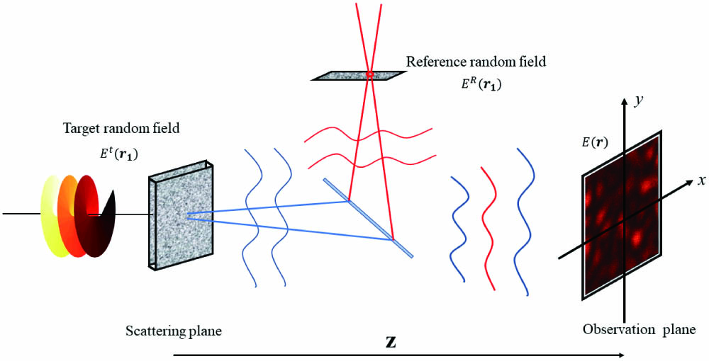
Fig. 1. Geometry of sources, scattering plane, observation plane, and propagation system.
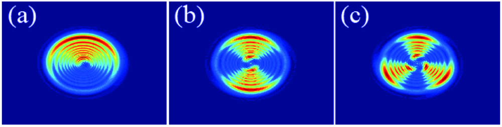
Fig. 2. Simulations of intensity pattern prior to the diffuser when the polarizer orientation is 45°. The topological charges of the vortex beams are 1, 2, and 3, respectively.
Fig. 3. Experimental setup for measuring the topological charge of the vortex beams from laser speckle. Laser, He–Ne laser; MO, microscope objective; P, pinhole;
Fig. 4. Experimental results and numerical simulations of the Fourier transform of the cross-covariance for the vortex beam with topological charge 1. (a)–(d) are the experimental results for rotation angles of polarizer 0°, 45°, 90°, and −45°. (e)–(h) are the simulations corresponding to (a)–(d), respectively.
Fig. 5. Experimental results and numerical simulations of the Fourier transform of the cross-covariance for vortex beam case without a polarizer. (a)–(c) are the experimental results for topological charges 1, 2, and 3. (d)–(f) are the simulations corresponding to (a)–(c), respectively.

Set citation alerts for the article
Please enter your email address
© Copyright 2018-2021 | Chinese Laser Press. All Rights Reserved 沪ICP备15018463号-20