• Photonics Research
  • Vol. 9, Issue 10, 2024 (2021)
Langlang Xiong1、2, Yu Zhang1、2、3, and Xunya Jiang1、2、3、*
Author Affiliations
  • 1Institute of Future Lighting, Academy for Engineering and Technology, Fudan University, Shanghai 200433, China
  • 2Engineering Research Center of Advanced Lighting Technology, Fudan University, Ministry of Education, Shanghai 200433, China
  • 3Department of Illuminating Engineering and Light Sources, School of Information Science and Engineering, Fudan University, Shanghai 200433, China
  • show less
    DOI: 10.1364/PRJ.423260 Cite this Article Set citation alerts
    Langlang Xiong, Yu Zhang, Xunya Jiang. Resonance and topological singularity near and beyond zero frequency for waves: model, theory, and effects[J]. Photonics Research, 2021, 9(10): 2024 Copy Citation Text show less

    Abstract

    Research interest in resonance and topology for systems at near-zero frequency, whose wavelength could be 2 orders larger than the scale of resonators is very rare, since the trivial effective-medium theory is generally thought to be correct in this regime. Also, the complex frequency regime is generally thought to be irrelevant to the topological properties of Hermitian systems. In this work, we find the general conditions to realize near-zero frequency resonance for a resonator and theoretically propose two kinds of realizations of such resonators, which are confirmed by numerical methods. The photonic crystals with such a resonator as the unit cell present rich topological characteristics at the near-zero frequency regime. The topological singularity that corresponds to the resonant frequency of the unit cell can be pushed to zero frequency at the bottom of the first band by tuning a certain parameter to a critical value. Surprisingly, we find that, when the parameter is tuned over the critical value, the singularity has disappeared in the first band and is pushed into the imaginary frequency regime, but now the topology of the first band and gap is still nontrivial, which is demonstrated by the existence of the topological edge state in the first gap, the negative sign of imaginary part of the surface impedance, and the symmetry property of Wannier functions. So, we are forced to accept that the singularity in the imaginary frequency regime can influence the topology in the real frequency regime. So, for the first time, to the best of our knowledge, we find that the singularity in the pure imaginary regime can still cause the observable topological effects on the real frequency regime, even for the Hermitian systems. Now, zero frequency acts as a novel exceptional point for Hermitian systems and the topology of the first band and first gap could be quite different from other bands and gaps, since they are intrinsically connected with zero frequency. Other new phenomena are also observed when the singularity is at the near-zero frequency regimes (real or imaginary), e.g., the cubic relationship between reflection coefficient and the frequency, the robust wide-bandwidth high transmission at very low frequency, etc. Besides the theoretical importance, some basic applications, such as the robust deep subwavelength wide bandwidth high-transmission layered structures, the subwavelength wide bandwidth absorbers, and the cavity from the topological subwavelength edge state are proposed, which can inspire new designs in many areas of optics, microwaves, and acoustics. This work opens a new window for rich topological physics and revolutionary device designs at the near and beyond zero-frequency regimes.

    1. INTRODUCTION

    In the traditional study of waves, the resonator is one of the most important concepts. The resonators are significant, since the stronger local field, the longer dwelling time, and the zero scattering at the resonant frequency, permit it to be widely used on devices of different applications. The complex media of waves, such as crystal systems that could be periodically composed of resonators, induce the revolution to understand complex wave behaviors and to design new devices beyond the traditional limit. Taking the photonic system as an example, with the introduction of photonic crystals (PhCs) [1,2], rich structural dispersion characteristics can be realized, such as photonic bandgap [3], low group velocity [4], self-collimation [5], and super prisms [6]. The needs for wave manipulation at the low-frequency regime widely exist in many fields, and it is worthwhile to devote more efforts to investigate this topic deeply. For the near-zero resonant frequency whose criterion is that the wavelength is about 2 orders larger than the scale of resonators, both concepts of resonators and crystal systems are facing challenges generally. First, the scale of traditional resonator design based on nondispersive (or weakly dispersive) material is generally comparable with the wavelength, which is obviously not suitable. For example, the smallest scale of Fabry–Perot (FP) cavity [7] is the half-wavelength of lowest resonant frequency. Recently, researchers have realized subwavelength resonators [8] mainly through the use of metamaterials [9]. The disadvantages of subwavelength metamaterial resonators are strong absorption and strong dispersion, complex microstructures, etc. Even more, the resonant wavelength of metamaterial resonators is still hard to get to 2 orders larger than the resonator scale. Second, for crystal systems, all designs seem useless at near-zero frequency range, since all structural materials turn out to be like some kind of homogeneous effective media. Actually, the effective medium theory [10] is widely accepted by researchers at the very low-frequency regime and is generally thought to be trivial in some way. For example, a PhC is generally replaced by an effective medium at the near-zero frequency, which is at the bottom of the first band.

    On the other hand, the topology study of different physics directions has grown into a burgeoning research area in recent years, for both quantum waves [1114] and classical waves [1520]. The topological singularity, which could be thought of as the position of topological charge with a certain gauge, is an important role for topology study. Especially for the periodic systems, the evolution of topological singularities between bands is the origin of topological phase transition, which are signed by the gap-closing-reopening process and nontrivial Chern number or Zak phase [2123]. It should be emphasized that the condition of the topological singularity of periodic systems is the zero amplitude wave function, which corresponds to the zero-scattering of the unit cell at resonant frequency [13,21]. Very recently, it was reported that the topological singularity could be observed on the first band [24,25]. The topology is widely studied not only for Hermitian systems, but also expanded to non-Hermitian systems [26]. For Hermitian systems, researchers generally are only concerned with the topology at the real frequency regime, while for non-Hermitian systems, the complex frequency is taken into account and new phenomena are reported, e.g., the exceptional points [27,28] in the complex frequency regime. So, there is an invisible “domain wall” between the real frequency regime and the complex frequency regime for Hermitian or non-Hermitian systems. However, in contrast with the rapid expansion of topological study in many directions, there has been almost no topology study of periodic systems at the near-zero frequency regime. We think the reason is that the widely-accepted effective medium theory implies the topological triviality at the near-zero frequency regime. To the best of our knowledge, so far the resonators and the topological singularity of the periodic systems, whose frequency can be tuned to zero and even be pushed beyond zero frequency by changing certain structural or material parameter(s), have not been investigated. For topology physics, it would be very novel and original to reveal that, beyond the effective medium theory, there are rich topological phenomena at the near-zero frequency range. Even more, we may have to pass through the “domain wall” between the real frequency regime and the imaginary frequency regime for the topological study of Hermitian systems at zero frequency, and find that the topologies in these two regimes are correlated even for Hermitian systems. Also the topology of the first band and the first gap could present characteristics different from other bands and gaps because they are intrinsically connected with zero frequency. Besides these important theoretical concerns, the deep-subwavelength resonators, the subwavelength low-reflection structures, and the high-Q subwavelength cavities based on the topologically protected edge states, are also fascinating from the view of potential applications in the direction of thin-film optics, lasers, enhanced subwavelength detectors, and microwave absorbers, etc.

    In this work, we systemically investigate the resonators with near-zero resonant frequency and the exotic topology near and beyond zero frequency for Hermitian PhCs that are composed of such resonators periodically. First, we construct a resonator model with a virtual interface in an FP cavity and find the required conditions for the zero resonant frequency through path integral formulation [29]. The simplest realizations to satisfy these conditions are to add a side-coupled subresonator or an embedded subresonator to the FP cavity. Theoretically and numerically, it is demonstrated that the resonant frequency of such model can be tuned to zero by changing a certain parameter to a critical value. Then, by periodically arranging these resonators as PhCs, we find the topological singularity at near-zero frequency, which is close to the bottom of the first band and which means the topological nontriviality of the first band and first gap. By changing the parameter to a certain critical value, we can tune the singularity to the zero frequency. New phenomena, such as the cubic relation between the reflection coefficient and the frequency, are found, which means the wideband high transmission is near zero frequency. Surprisingly, when the parameter is tuned over the critical value and the singularity is pushed beyond zero frequency and disappears from the first band, we find that the first band and the first gap are still topologically nontrivial, which is demonstrated by the existence of the topological edge state, the sign of the impedance imaginary part from the reflection, and the property of Wannier function (WF). Such anti-intuitive results force us to accept the mathematical explanation that the topological singularity still exists in the imaginary frequency regime even if our systems are Hermitian. In other words, the zero-frequency point is a special exceptional point for Hermitian systems, and the singularity in the imaginary frequency regime can cause detectable physical results, e.g.,  the topological edge state, the change of the sign of the surface impedance imaginary part, and the parity property of the Wannier function of the first band (WFFB). Not only theoretical importance, but also different engineering applications are presented in this work, such as the robust deep subwavelength wideband high transmission layers, the subwavelength wideband absorbers, and the lasers based on the subwavelength topological edge states. These applications can bring new concept designs to various fields of optics and microwaves, even other waves, e.g.,  acoustic waves.

    2. MODEL

    The model we start with is a virtual interface embedded at the center of the FP cavity, as shown in Fig. 1. The question is what conditions can realize the near-zero frequency resonant transmission in such a general model. We assume the FP cavity is a dielectric layer with the relative permittivity and permeability εb and μb and thickness db in the background medium with εa and μa. We suppose μa=μb=1. The transmission coefficient ti and reflection coefficient ri of forward incidence and the transmission coefficient ti and reflection coefficient ri of the reverse incidence of the three interfaces are shown in Fig. 1 (where i=1,2,  3). In order to achieve near-zero frequency resonance, from the backscattering view, the reflection coefficient of the virtual interface must satisfy a certain phase and amplitude, such that the perfect canceling (destructive interference) happens at all backscattering waves from the three interfaces. We can use the path integral formulation to strictly analyze the destructive interference; details are given in Appendix A. The conclusion from the path integral analysis is that there are two conditions to realize the near-zero frequency resonance: (i) r2exp(ikbdb) is a pure imaginary number, where kb=2πεbμbf/c, f is frequency; (ii) r2=r2, which can be easily satisfied if the spatial inversion symmetry [29] is guaranteed. If we suppose r2 has the general form r2=iωα at near-zero frequency [30], where ω=2πf, α is independent of the frequency; its physical meaning will be explained later. So, the first condition of near-zero frequency resonance becomes r2exp(ikbdb)iωα(1+ikbdb)iωα.

    Abstract model that could have near-zero frequency resonance, which can be regarded as a virtual interface embedded at the center of the FP cavity.

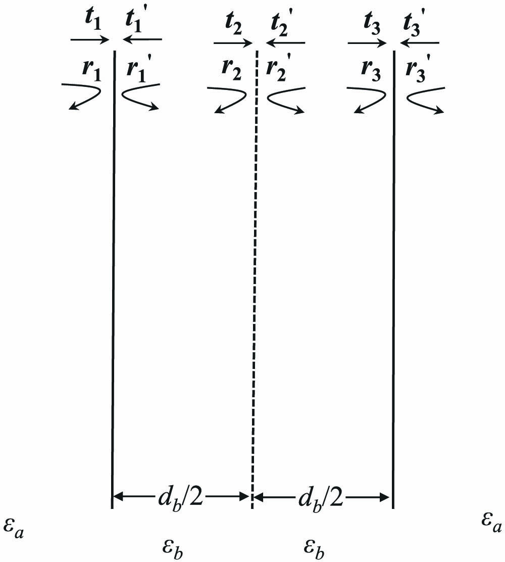
    Figure 1.Abstract model that could have near-zero frequency resonance, which can be regarded as a virtual interface embedded at the center of the FP cavity.

    The general model shown in Fig. 1 can be realized in many ways, e.g.,  two partial reflectors and a side-coupled or embedded subresonator, as schematically shown in Fig. 2(a). Two concrete realizations are shown in Figs. 2(b) and 2(c): one is a layered waveguide with a side-coupled stub, and the other is an FP cavity with an embedded dielectric layer. Generally, the scattering property of the side-coupled or embedded subresonator at the near-zero frequency can be described by the transfer matrix M [29], M=[t2r2r2t2r2t2r2t21t2][1+iωαiωαiωα1iωα].Actually, based on the strict transfer matrices, we can go through the whole above discussion without any approximation and show that the resonant frequency can evolve from the low-frequency range to the near-zero frequency range. However, for the near-zero frequency range, the path integral analysis can give a simple and intuitive picture to understand such systems. We hope to emphasize here that this near-zero frequency resonance phenomenon is based on a simple interference picture, so it should be universal for different waves, not only for electromagnetic (EM) waves, but also acoustic waves, mechanical waves, and other waves.

    Physical realizations of the resonator with near-zero frequency resonance. (a) General realization with two partial reflectors and a side-coupled or embedded subresonator; (b) physical realization of a side-coupled stub waveguide; (c) physical realization of a layered structure with an embedded FP cavity.

    Figure 2.Physical realizations of the resonator with near-zero frequency resonance. (a) General realization with two partial reflectors and a side-coupled or embedded subresonator; (b) physical realization of a side-coupled stub waveguide; (c) physical realization of a layered structure with an embedded FP cavity.

    3. SIDE-COUPLED SUBRESONATOR EXAMPLE WITH NEAR-ZERO FREQUENCY RESONANCE

    In this section, we provide an example of near-zero frequency resonance that satisfies the resonant conditions in Section 2. As shown in Fig. 2(b), the model consists of a waveguide and a side-coupled stub. Two mirrors of an FP cavity are from the interfaces of two kinds of filled dielectric materials in the waveguide, whose relative permittivity and permeability are εa=4 and μa=1 (kind A) and εb=6.25 and μb=1 (kind B), respectively, and the thicknesses of kind A and kind B are da and db. The length of the stub is ls, and we suppose the material filled in the stub is the same as B-kind material (not required) with εs=εb=6.25 and μs=μb=1. Not only EM waves, but also the transfer matrix of the side-coupled stub is also widely studied in acoustic and matter waves [24,31,32]. For both transverse electric (TE, Ez polarization) and transverse magnetic (TM, Hz polarization) modes of the EM wave, its reflection coefficient can be described as r2=itanksls2+itanksls, where ks=εsμsω/c. When the frequency is close to zero, the reflection coefficient of the stub is purely imaginary, since r2iksls2+ikslsiksls2. With the spatial inversion symmetry of the structure, the conditions discussed in Section 2 are satisfied, and we find α=εsμsls2c for such a system. Based on the transfer matrix of the whole system, we can easily obtain the strict relation between the resonant frequency fc and the stub length ls for the TM mode (similar derivation can be done for TE mode) as ls=1ksarctan[2ks(ka2kb2)kbsin(kbdb)(ka2kb2)cos(kbdb)+ka2+kb2],where kj=2πεjμjfc/c (j=a,b,s). For the low-frequency approximation, the relation also can be approximated as lsdb(εbεa)εa(12εbπ2db3fc23c3).It is interesting that the critical length of stub lc=db(εbεa)/εa, which corresponds to zero resonant frequency, is finite and independent from εs (in the Ez polarization case, it is dependent). The curve of resonant frequency versus stub length when da=0.5  mm and db=1  mm is shown in Fig. 3 with a black solid line. Obviously, by tuning the ls to the critical value lc, the resonant frequency fc will decrease to zero. With the parameters defined above, the critical length of the stub is ls=lc=0.563  mm. We notice that if ls>lc, the resonant frequency is a pure imaginary number from Eq. (3), which seems irrational from the general understanding of resonance. However, we will see in the next sections that such imaginary resonant frequency is relevant for topological study.

    Resonant frequencies versus the stub length ls with da=0.5 mm, db=1 mm, εa=4, εb=εs=6.25, and μa=μb=μs=1. The black solid line represents the calculated result of TMM, and the blue square, red circles, and green line with asterisks represent the result of FEM with different widths of waveguide and stub W=1 μm, 5 μm, and 100 μm, respectively. The result of silver substrate with W=100 μm is plotted as cyan diamonds.

    Figure 3.Resonant frequencies versus the stub length ls with da=0.5  mm, db=1  mm, εa=4, εb=εs=6.25, and μa=μb=μs=1. The black solid line represents the calculated result of TMM, and the blue square, red circles, and green line with asterisks represent the result of FEM with different widths of waveguide and stub W=1  μm, 5 μm, and 100 μm, respectively. The result of silver substrate with W=100  μm is plotted as cyan diamonds.

    To verify the correctness of our results from the transfer-matrix method (TMM), we use the finite-element method (FEM) as the numerical experiments to obtain the resonant frequency of the system. The waveguide and the stub in Fig. 2(b) are supposed to be covered by the perfect electrical conductor (PEC), which generally is a good approximation for metals in the microwave frequency range. In Fig. 3, the resonant frequencies versus the stub length ls with different widths of the waveguide and stub W=1,5, and 10 μm are shown by blue squares, red circles, and a green line with asterisks. From the numerical results of Fig. 3, we emphasize that all results from FEM simulation with different W will go to zero frequency at a certain critical length, which shows the near-zero frequency resonance is a very robust phenomenon for such systems. For deviation between TMM and FEM results for large W, it can be explained that, when the W is large, “the effective length” leff of the stub is a little larger than its real length ls, so that the strict resonant frequency of the whole system shifts to a lower one for a stub with larger W in Fig. 3.

    To test this phenomenon on real systems, we have also done the FEM calculation with real material, e.g.,  silver. With silver substituting the PEC and setting all other parameters the same as before, the resonant frequency versus stub length ls for W=100  μm is shown in Fig. 3 by cyan diamonds. Obviously, the results of silver are very similar to those of PEC.

    4. TOPOLOGICAL SINGULARITY WITH FREQUENCY APPROACHING AND BEYOND ZERO OF PERIODIC SYSTEM

    The topology of the bandgap structure from periodic systems has attracted much attention in recent years. The topological phase transition of the bandgap structure can be explained by the evolution of topological singularity. Physically, the zero-scattering property [21] and the phase vortex point of the reflection coefficient in parameter space [22,33] are the signs of topological singularity. If we can construct a periodic system (crystal structure) by the unit cell that is the same as the near-zero frequency resonator discussed above, can we find new topological phenomena in such systems? Even more, can we go beyond zero frequency and find new topologies for the bandgap structure? Next, we will show that new phenomena and special topology are found for such periodic systems with near-zero frequency singularity.

    First, a periodic system is constructed by the unit cell, which is shown in Fig. 4. Now, we set the distance Δ from the center of the stub to the center of layer-A as a free parameter, also called the “synthetic dimension” for topological study. So, the phase and the amplitude of reflection coefficient r of half-infinite periodic model can be analyzed at the two-dimensional parameter space {f,Δ/a} [22,33], where a is the lattice constant. Other parameters are set as da=db=1  mm, ls=0.56  mm, εa=4, εb=εs=6.25, μa=μb=μs=1, and the lattice constant is a=2  mm. By using TMM, the diagrams of the phase of reflection coefficient r and the reflection of a half-infinite periodic structure at {f,Δ/a} space can be obtained. The results are shown in Fig. 5. The phase vortex point in the reflection phase map and the almost zero reflection can be clearly seen at the low-frequency resonant point with the conditions that we have discussed in previous sections. This point is a topological singularity that will be demonstrated later. The ratio of frequency fs of topological singularity to the frequency of the upper edge of the first band is about 1/12.95 and can be tuned to zero step by step. This is the first time to find a topological singularity near the bottom of the first photonic band that can be very close to zero frequency. According to the path integral formulation in Appendix A and the trajectory of singularity in Fig. 3, we can see that the near-zero frequency topological singularity could widely exist for periodic systems with the unit cell, which is composed of an FP cavity and a side-coupled or embedded subresonator.

    Periodic arrangement of the structure in Section 3. We set the distance Δ from the center of the stub to the center of layer-A as a free parameter, also known as synthetic dimension.

    Figure 4.Periodic arrangement of the structure in Section 3. We set the distance Δ from the center of the stub to the center of layer-A as a free parameter, also known as synthetic dimension.

    Reflection phase and reflectivity projection band diagram at the synthetic dimension Δ/a and frequency.

    Figure 5.Reflection phase and reflectivity projection band diagram at the synthetic dimension Δ/a and frequency.

    The topological singularity can be strictly verified for such periodic systems with several methods. The first method is more mathematical, in which we can judge the topological properties of the band by the number of resonant peaks in each band [34]: a band with a topological singularity has N peaks, and a band without topological singularity has N1 peaks, where N is the number of PhC cells. The second method is more physical, in which two kinds of PhCs with opposite topological properties in a common gap frequency range will have the different sign of the imaginary part of the surface impedance and a topological edge state will appear at the interface if we connect two PhCs together [21]. So, we construct four kinds of finite PhCs with 10 cells by fixing Δ/a=0.5, μa=μb=μs=1 and changing other parameters, whose first, second, and third bands are marked as B1, B2, and B3, respectively. The first PhC-A, with parameters of da=1.35  mm, db=0.75  mm, εa=4, εb=εs=6.25, and ls=0  mm, has no topological singularity at the first and second bands, but has a topological singularity at the third band, as shown in Fig. 6(a). The second PhC-B, with da=1.05  mm, db=1  mm, εa=4, εb=εs=6.25, and ls=0  mm, has a topological singularity at the second band and no singularity at the first and third bands, as shown in Fig. 6(b). The third PhC-C, with da=0.8  mm, db=1  mm, εa=4, εb=εs=6.25, and ls=lc=db(εbεa)/εa=0.563  mm, has a topological singularity at the zero frequency and no singularity at the second and third bands, as shown in Fig. 6(c). The fourth PhC-D, with da=1  mm, db=1  mm, εa=4, εb=εs=6.25, and ls=0.6  mm>lc, which means the singularity is pushed over the zero frequency, is shown in Fig. 6(d).

    Reflection coefficient for four kinds of finite PhCs with N=10 cells. The first, second, and third bands are marked as B1, B2, and B3, respectively. (a) PhC-A, da=1.35 mm, db=0.75 mm, εa=4, εb=εs=6.25, and ls=0 mm; (b) PhC-B, da=1.05 mm, db=1 mm, εa=4, εb=εs=6.25, and ls=0 mm; (c) PhC-C, da=0.8 mm, db=1 mm, εa=4, εb=εs=6.25, and ls=lc=db(εb−εa)/εa=0.563 mm; (d) PhC-D, da=1 mm, db=1 mm, εa=4, εb=εs=6.25, and ls=0.6 mm>lc.

    Figure 6.Reflection coefficient for four kinds of finite PhCs with N=10 cells. The first, second, and third bands are marked as B1, B2, and B3, respectively. (a) PhC-A, da=1.35  mm, db=0.75  mm, εa=4, εb=εs=6.25, and ls=0  mm; (b) PhC-B, da=1.05  mm, db=1  mm, εa=4, εb=εs=6.25, and ls=0  mm; (c) PhC-C, da=0.8  mm, db=1  mm, εa=4, εb=εs=6.25, and ls=lc=db(εbεa)/εa=0.563  mm; (d) PhC-D, da=1  mm, db=1  mm, εa=4, εb=εs=6.25, and ls=0.6  mm>lc.

    With the first judgment, we can count the number of resonant peaks, which are signified by the almost zero reflectivity of the four kinds of PhCs with N=10 cells. When we tune ls length gradually and the PhC evolves from PhC-B type to PhC-C type, it is found that the first gap will close and reopen when the topological singularity moves from the second band to the first band, and the resonant peaks of the first band will change from 9 to 10 and vice versa. So a typical topological phase transition is demonstrated in this process.

    With the second judgment by the topologically protected edge state, we can splice PhC-A, PhC-C, and PhC-D (5 cells) with PhC-B (10 cells), respectively; the absolute value of the reflection coefficient is shown in Figs. 7(a)–7(c). According to the well known “bulk-edge correspondence,” when two kinds of PhCs with the same gap frequency range but opposite topological properties are connected, there must be a topological edge state in the corresponding gap. In the PhCs, the “opposite topological properties” mean the difference sign of ς=Zs/(iZ0), where Zs is the surface impedance of a half-infinite PhC and Z0 is the vacuum impedance, which is consistent with Zak phases and the evolution of singularities on different bands [21]. The condition for the occurrence of the topological edge states is ZSR+ZSL=0, where R and L mean the right and left sides for the interface between the spliced PhCs. With this condition, we can accurately predict the specific frequency of the edge state appearing. We present the field distribution |H(x)| of the edge states in the insets of Fig. 7, and the interface between PhCs is marked with red dashed lines. We can find that these field distributions satisfy the characteristics of the edge states, which should be localized at the interfaces.

    Reflection coefficient and magnetic field of the edge state. (a) Splice PhC-A (5 cells) with PhC-B (10 cells); (b) splice PhC-C (5 cells) with PhC-B (10 cells); (c) splice PhC-D (5 cells) with PhC-B (10 cells).

    Figure 7.Reflection coefficient and magnetic field of the edge state. (a) Splice PhC-A (5 cells) with PhC-B (10 cells); (b) splice PhC-C (5 cells) with PhC-B (10 cells); (c) splice PhC-D (5 cells) with PhC-B (10 cells).

    We compute the sign of ς and show the results in Table 1. From Fig. 6 and Table 1, the second gap of PhC-A and PhC-B and the first gap of PhC-B and PhC-C have opposite topological properties. Hence, the topological edge states are found in these gaps, as shown in Figs. 7(a) and 7(b). So, the existence of topological edge state in the first gap in Fig. 7(b) shows that the near-zero frequency topological singularity really can change the topological property of the first band, and there is a topological phase transition in the evolving process from PhC-B type to PhC-C type. It should be emphasized that the sign of ς for the first gap will not change when the topological singularity is tuned from zero frequency to another frequency of the first band.

    Sign of ς for Different PhCs and Different Gaps

    GapPhC-APhC-BPhC-CPhC-D
    First gap<0<0>0>0
    Second gap>0<0<0<0

    Interestingly, there are topological edge states in the first gap, as shown in Figs. 7(b) and 7(c) because the first bands are nontrivial in PhC-C and PhC-D. Since the wavelength in the first gap is much longer than other gaps, it is possible to realize the subwavelength edge states, as shown in Fig. 7(b). This phenomenon has not been reported in the photonic topological edge state, since the first band is generally trivial. More particularly, the edge state is very robust and topologically protected. The high-Q cavity based on the subwavelength topological edge state with enhanced field density at the interface can be widely used in a subwavelength laser, enhanced subwavelength detector, etc.

    We notice that there are new phenomena for the zero-frequency singularity. The first interesting phenomenon for the zero-frequency singularity is that the derivative of the absolute value of reflection coefficient |r|/f could be zero around the singularity, as shown in Fig. 6(c). This property is quite different from the singularities with the finite derivative of |r| shown in Figs. 6(a), 6(b), and 6(d). Theoretically, we can derive that |r|f3 at the neighbor frequency range of a zero-frequency singularity; the detailed derivation is given in Appendix B. Physically, such a cubic function is from the destructive interference of the backscattering between the stub and the FP cavity. For zero frequency, the backscattering of a cavity is generally composed of a linear frequency term and cubic frequency term, etc. For our system with zero-frequency singularity, since the linear frequency terms of the FP cavity and the stub are canceled out by each other, the cubic terms become dominant. This abnormal phenomenon ensures that the reflectivity is very low through the whole neighborhood of the low-frequency range, which also means robustness for observing the zero-frequency singularity.

    Another interesting phenomenon is revealed to answer the question “What will happen for the topological properties of the bandgap structure if we tune the stub length ls over (larger than) lc and push the singularity beyond the zero frequency?”. This is the reason we constructed the PhC-D in this work. From the view of no-singularity at the first band as shown in Fig. 6(d) by the |r|, there seems to be a topological phase transition in the process. However, from another view of gap-closing-reopening, there seems no topological phase transition. We check the topological edge state in Fig. 7(c) and surprisingly find that there is still a topological edge state even when we push the singularity over the zero frequency. Obviously, the topological edge state is physically observable, so we have to accept the conclusion that there is no topological phase transition, even if we push the singularity beyond the zero frequency and the topological property of the first band keeps nontrivial in the process. How to understand this counterintuitive conclusion is very tricky. First, from Table 1, we can see that the signs of ς of the first gap is the same for both PhC-C and PhC-D, which means the first gap of both PhCs are topologically nontrivial compared with the first gap of “common” PhCs. Second, if we still hope to explain the topological nontriviality of the PhC-D first gap from the evolution of singularity, we need to go back to Eq. (2) and find the further evolution of singularity for the cases with ls>lc. It is found that, for ls>lc, Eq. (2) still can be sustained if we extend our real-valued frequency regime to the complex frequency regime. In the complex frequency regime f=fr+ifi, the trajectory of singularity can be drawn in space {fr,fi,ls}, as shown in Fig. 8. From the trajectory in the complex regime of frequency, the singularity is pushed beyond the zero frequency into the pure imaginary regime with fr=0. We argue that the real frequency regime is always intrinsically connected with the pure imaginary frequency regime at the origin point with fr=0 and fi=0, so that pushing singularity from the real frequency regime into the pure imaginary regime does not change the topological properties of PhC. Generally, the complex frequency regime is of concern only for the non-Hermitian systems. For our system, we suppose it is a Hermitian one, since the absorption of PEC is zero, and the Hermitian property is more obvious for the dielectric layered system, to be discussed in the next section. But now, to explain the topological property of the first band and the topological edge state in the first gap from the evolution of singularity, we have to face the singularity in the pure imaginary regime. In other words, we find a specific case in which the system is supposed to be a Hermitian one, and the singularity in the pure imaginary frequency regime can cause the physically detectable effects on the topology of the bandgap structure, i.e., the existence of topological edge state. Mathematically, we show that the zero-frequency point is a special exceptional point for Hermitian systems, and the singularity in the imaginary frequency regime is connected to the first band in the real frequency regime.

    Trajectory of singularity in space {fr,fi,ls}.

    Figure 8.Trajectory of singularity in space {fr,fi,ls}.

    5. SINGULARITY OF LAYERED PHOTONIC CRYSTALS AND APPLICATIONS

    As discussed above, the near-zero frequency resonance can be realized not only for the model with the side-coupled cavity, but also for the model with an embedded cavity, as shown in Fig. 2(c). We will demonstrate that the resonance frequency of such a simple dielectric layered model can be tuned to zero, and the PhCs with such a model as a unit cell also can exhibit exotic topological properties for the first bandgap. The advantages of the dielectric layered model are that (i) no PEC or metal substrate is needed for the model, and the Hermitian property of the model is obvious; (ii) the structure is very simple so that it could be easily realized by real material; (iii) wide usages, such as the subwavelength perfect absorber or the deep subwavelength no-reflection film at wide frequency range, could be expected for some special applications, even considering the technology limit.

    For the layered model shown in Fig. 2(c), we assume a layer-C with thickness dc, which substitutes the abstract mirror shown in Fig. 1, and is embedded in the middle of the FP cavity that is composed of a layer B with thickness db=1  mm in the background material-A with thickness da=1  mm. The permittivity and permeability of layer-A, layer-B, and layer-C are fixed as εa=4, εb=1.5, εc=9, and μa=μb=μc=1. We set dc as a variable to compute the resonant frequency of this layered model in space {f,dc} by TMM, and the result is shown in Fig. 9(a) with the black dashed line. We find that the trajectory of resonant frequency could go to zero when tuning the thickness of layer-C to the critical thickness dc=dc0. Through theoretical derivation, we can obtain the relation between the layer-C thickness dc and the resonant frequency fc with low-frequency approximation as dc(εbεa)dbc2(εaεc)c2+π2(εb2εaεc)db2fc2.For zero-resonant frequency, we can obtain the critical thickness of layer-C as dc0=(εbεa)dbεaεc. With the structural and material parameters defined above, we can obtain the critical thickness as dc0=0.5  mm. Similar to the side-coupled cavity model in the previous section, we also notice that Eq. (4) can still be satisfied when dc>dc0 if the imaginary frequency is considered.

    (a) Black dashed line, the trajectory of singularity in space {dc,f}; parameters are set as da=db=1 mm, εa=4, εb=1.5, and εc=9; color map, reflectivity of layered structure in space {dc,f} with loss and randomness; parameters are set as ε^m=εm+0.003iεm, d^m=dm(1+W·γ), where m=a,b,c, W=0.01 is random strength, γ is an evenly distributed random number in the range [−1,1]; (b) reflection coefficient of PhC-E with da=1.4 mm, db=1 mm, dc=0.2 mm, εa=4, εb=1.5, εc=9, and N=10; (c) reflection coefficient of PhC-F with da=1 mm, db=1 mm, dc=dc0=0.5 mm, εa=4, εb=1.5, εc=9, and N=10; (d) reflection coefficient of PhC-G with da=1.2 mm, db=1 mm, dc=0.55 mm>dc0, εa=4, εb=1.5, εc=9, and N=10; (e) reflection coefficient and electric field of the edge state by splicing PhC-F (5 cells) with PhC-E (15 cells); (f) reflection coefficient and electric field of the edge state by splicing PhC-G (5 cells) with PhC-E (15 cells).

    Figure 9.(a) Black dashed line, the trajectory of singularity in space {dc,f}; parameters are set as da=db=1  mm, εa=4, εb=1.5, and εc=9; color map, reflectivity of layered structure in space {dc,f} with loss and randomness; parameters are set as ε^m=εm+0.003iεm, d^m=dm(1+W·γ), where m=a,b,c, W=0.01 is random strength, γ is an evenly distributed random number in the range [1,1]; (b) reflection coefficient of PhC-E with da=1.4  mm, db=1  mm, dc=0.2  mm, εa=4, εb=1.5, εc=9, and N=10; (c) reflection coefficient of PhC-F with da=1  mm, db=1  mm, dc=dc0=0.5  mm, εa=4, εb=1.5, εc=9, and N=10; (d) reflection coefficient of PhC-G with da=1.2  mm, db=1  mm, dc=0.55  mm>dc0, εa=4, εb=1.5, εc=9, and N=10; (e) reflection coefficient and electric field of the edge state by splicing PhC-F (5 cells) with PhC-E (15 cells); (f) reflection coefficient and electric field of the edge state by splicing PhC-G (5 cells) with PhC-E (15 cells).

    Next, we will study the topological properties of the PhCs with the model shown in Fig. 2(c) as the unit cell. Three kinds of PhC structure are constructed, with the rules that we fix the permittivity and permeability of all layers and the layer-B thickness db as before, and change the thickness of layer-A da and layer-C dc to control the overlapping frequency range of the first gap and to tune the position of singularity. The three PhCs are: the PhC-E with da=1.4  mm and dc=0.2  mm, which has a singularity at the second band and no singularity at the first band; the PhC-F with da=1  mm and dc=dc0=0.5  mm, which has a singularity at the zero frequency; and the PhC-G, with da=1.2  mm and dc=0.55  mm>dc0, whose singularity is pushed beyond the zero frequency into the pure imaginary frequency regime. The absolute value of the reflection coefficient |r| of those PhCs with 10 cells is shown in Figs. 9(b)–9(d), while the first three bands are also marked as B1, B2, and B3. Many characteristics of |r| are similar to the PhCs composed of the side-coupled model, such as the |r|f3 and |r|/f is zero if the singularity is close to zero as shown in Fig. 9(c), and the sign of the imaginary part of the surface impedance ς keeps the same from PhC-F to PhC-G, which reminds us the unchanged topological properties when the singularity is pushed beyond zero frequency.

    Furthermore, we connect the PhC-F and the PhC-G with 5 cells with PhC-E with 15 cells, respectively, to verify the existence of edge states, whose reflection spectra are shown in Figs. 9(e) and 9(f), while the field distribution |E(x)| of the edge states is also shown in the insets. The edge states can be found at the first gap in both systems with two connected PhCs. Hence, for the dielectric layered PhCs, which are obviously Hermitian, we also have to face the phenomenon that the singularity in the imaginary frequency regime will cause the detectable physical effects in the real frequency regime, e.g.,  the existence of topological edge state in the first gap. We would note that it is also possible to realize the subwavelength high-Q cavity owing to the topologically protected edge state in the first gap, which can be widely used in different areas of optics and microwaves.

    Because of the simplicity of the layered system, we have also investigated the WF of such systems. It is widely known that if we choose a certain spatial-inversion-symmetry center as the Wannier center, the well-localized WF with certain parity symmetry around that Wannier center is the judgment of the topological triviality for a band [3537]. In other words, if we cannot find such a well-localized WF around a chosen Wannier center for a certain band, that means the topological nontriviality of that band. We find that this judgment is correct for other bands, but it will face a new challenge for the first band, which is intrinsically connected with zero frequency. We set the parameters to da=db=1  mm, and permittivity and permeability are the same as before. When we choose the center of the C-kind layer in our layered model as the symmetry center and tune the singularity from the second band to the first band, then to the pure imaginary frequency continuously (through the zero frequency) by changing the thickness dc of layer-C, we find that the WFFB evolves in the following way. The WFFBs in this process are shown in Figs. 10(a)–10(g). First, when the singularity is at the second band with dc=0.2  mm, both the first band and first gap are topologically trivial and the WFFB is a real well-localized odd function, which is shown in Fig. 10(a). When we increase dc to 0.35 mm, the singularity is at the center of the first band. Now, the real part and the imaginary part of WFFB shown in Figs. 10(b) and 10(c) have different parity symmetry and are not well localized because of the topological nontriviality of the first band. But when we tune the singularity to a very low frequency at the first band with dc=0.49  mm, the real part of the WFFB shown in Fig. 10(d) decreases to a very small value, while the imaginary part of the WFFB shown in Fig. 10(e) becomes dominant and more localized. When the singularity is tuned to zero frequency with dc=dc0=0.5  mm, the real part of the WFFB is almost zero and negligible, as shown in Fig. 10(f) by the red line, so that the WFFB only has the imaginary part, which is a well-localized even function, as shown in Fig. 10(f) by the black line. When the singularity is tuned further into the imaginary frequency regime with dc=0.6  mm, the WFFB stays as the well-localized even imaginary function, as shown in Fig. 10(g). Comparing the WFFB with that in Fig. 10(a) of the topologically trivial case, we can clearly see the parity difference even if there is no singularity on the first band. Such parity difference of the WFFB assures us of the topological nontriviality when there is a singularity at imaginary frequency regime from the view of the WF and could also be used to explain the existence of the topological edge state, as shown in Fig. 9(f). So, the first band could be very special from other bands since its WFFB can have certain parity symmetry and still is topologically nontrivial, as shown in the case of Fig. 10(g). Based on the observation of the WFFB evolving, we still have to accept that the topology of the first band and the first gap could be influenced by the singularity in the imaginary frequency regime.

    WFFB with da=db=1 mm, εa=4, εb=1.5, and εc=9. (a) Real part of WFFB with dc=0.2 mm; (b) real part of WFFB with dc=0.35 mm; (c) imaginary part of WFFB with dc=0.35 mm; (d) real part of WFFB with dc=0.49 mm; (e) imaginary part of WFFB with dc=0.49 mm; (f) imaginary part (black line) and real part (red line) of WFFB with dc=0.5 mm; (g) imaginary part of WFFB with dc=0.6 mm.

    Figure 10.WFFB with da=db=1  mm, εa=4, εb=1.5, and εc=9. (a) Real part of WFFB with dc=0.2  mm; (b) real part of WFFB with dc=0.35  mm; (c) imaginary part of WFFB with dc=0.35  mm; (d) real part of WFFB with dc=0.49  mm; (e) imaginary part of WFFB with dc=0.49  mm; (f) imaginary part (black line) and real part (red line) of WFFB with dc=0.5  mm; (g) imaginary part of WFFB with dc=0.6  mm.

    Besides the theoretical importance of the near-zero frequency resonance and the exotic topological phenomena for PhCs, several applications with such simple structures can be considered directly. The first application is a deep subwavelength film with high transmittance and low reflectivity whose thickness could be one percentage of wavelength. Even with the randomness of the thickness of all layers and the small absorption of materials (ε^m=εm+0.003iεm, where m=a,b,c), which is determined by the technology limit, we can still obtain a very low average reflectivity in a wide frequency range near-zero frequency. We calculate the average reflectivity for 1000 configurations of randomness, as shown in Fig. 9(a), with the thickness of layer-A, layer-B, and layer-C set to da(1+W·γ), db(1+W·γ), and dc(1+W·γ), respectively, where W=0.01 is random strength and γ is an evenly distributed random number in the range [1,1]. The reflectivity can be as low as 50  dB in the frequency range from almost 0 to 5 GHz, as the black dashed arrow shows in Fig. 9(a). So, such a high-transmission phenomenon is very robust in the wide frequency range against randomness. Comparing low-reflection range lower than 50  dB of random systems (dashed arrow) with that of the normal one (solid arrow), we find that the high-transmission frequency range is even enhanced by randomness in some way, which is also an interesting phenomenon for the near-zero frequency resonant systems. We think this occurs because the resonant trajectory of the periodic system, shown by the dashed line in Fig. 9(a), is perpendicular to the horizontal axis near-zero frequency, and randomness extends the strict resonant condition into quasi-resonance in a wider range. This application would be useful in thin-film optics.

    Another application is the broadband subwavelength absorbers, which can absorb waves almost perfectly. A finite 1D PhC of such layered structure as a unit with the absorbing material can easily realize an ideal absorber. To show this property, we designed the absorber of EM waves with the ideal PEC as the base. Our goal is to realize reflectivity of less than 20  dB in a broad frequency range around the central frequency 10 GHz. In our calculation, the lossy materials of different layers are set as εa=16+3i, εb=9+1i, εc=25+8i, and μa=μb=μc=1, the thickness of layer-A and layer-B as da=db=0.8  mm, and the total thickness of finite PhC is chosen as 10 periods. The reflectivity of the layered structure with EM waves input from layer-A is shown in Fig. 11 with the thickness of layer-C set as 0.4 mm (black dotted-dashed line), 0.5 mm (black solid line), and 0.6 mm (black dashed line), respectively. All of those 1D PhCs show the subwavelength absorption property, and their lattice constants are only about 8% of the wavelength corresponding to 10 GHz. From the results of dc=0.5  mm shown in Fig. 11, the range of reflectivity lower than 20  dB is wider than 9 GHz, which means 90% bandwidth of high absorption. When the thickness of layer-C increases to dc=0.6  mm, the absorption frequency moves to a lower-frequency range, and there is an almost perfect absorption point whose reflectivity can be less than 50  dB at frequency 8.74 GHz. Such perfect absorption phenomena have also been reported in the high-frequency range [22,28] and are for the first time being found in the subwavelength case. The application could be used in the microwave anechoic chamber, reducing radar cross section, etc.

    Reflectivity of periodic structure with εa=16+3i, εb=9+1i, εc=25+8i, da=db=0.8 mm, and N=10. The black dotted-dashed line, black solid line, and black dashed line represent dc=0.4 mm, 0.5 mm, and 0.6 mm, respectively.

    Figure 11.Reflectivity of periodic structure with εa=16+3i, εb=9+1i, εc=25+8i, da=db=0.8  mm, and N=10. The black dotted-dashed line, black solid line, and black dashed line represent dc=0.4  mm, 0.5 mm, and 0.6 mm, respectively.

    6. CONCLUSIONS

    In summary, we have studied the resonance of the cavity and the singularity of PhCs near and beyond zero frequency. The results, such as the general conditions of resonance near-zero frequency and different designs to realize such resonance, e.g.,  an FP cavity with a side-coupled or embedded subresonator, are presented, which are confirmed by both theoretical and numerical methods. The PhCs with such a cavity as a unit cell are also studied. The topological singularities that can be tuned to zero frequency by changing certain structural (or material) parameters are found, and the topological nontriviality of the first band and gap is confirmed by the topological edge state. Counterintuitively, we observe that when the parameter is tuned over the critical value, which corresponds to the zero-resonant frequency, the topology of the first band and gap is still topologically nontrivial because of the existence of the topological edge state and the negative sign of the imaginary part of PhC surface impedance. From the mathematical analysis, we conclude that the singularity is pushed beyond zero frequency into the pure imaginary frequency regime. So, for the first time, we find the cases that the singularity in the pure imaginary regime can still cause observable effects on the real frequency regime, even if the systems in our study are Hermitian. Other new phenomena are also observed, e.g.,  the cubic relation between reflection and frequency when the singularity is tuned near-zero frequency, the wideband high transmission, which is robust against randomness. Besides the theoretical importance, some basic applications, e.g.,  the deep subwavelength wideband layered structures, the subwavelength wideband absorbers, and the high-Q cavities based on the subwavelength topological edge state, are proposed. Since the study of (extremely) low-frequency range is generally dominated by the effective medium theory, this work opens a new window to view the new topological physics and the possible revolutionary designs near and beyond zero frequency. Based on this work, various fields of optics and microwaves can be enlightened, e.g.,  thin-film optics, microwave anechoic chambers, subwavelength lasers, and enhanced subwavelength detectors, which also could be extended to the use of other waves, such as the biomedical imaging based on acoustic waves. Our topological research on near-zero frequency can also be helpful to further simplify and downscale compact systems, e.g.,  the coaxial waveguide and dielectric resonator antenna [38]. Further topics, such as what conditions we need to consider because of the influence from the imaginary frequency regime, other observable topologically nontrivial phenomena in the real frequency domain because of the singularity in the imaginary frequency regime for Hermitian or non-Hermitian systems, and the special role of zero frequency in the topology study, are waiting to be investigated. The related phenomena for high-dimensional systems and other waves, e.g.,  acoustic waves, machine waves, and matter waves, are also interesting topics.

    APPENDIX A: PATH INTEGRAL FORMULATION OF NEAR-ZERO FREQUENCY RESONANCE

    In this Appendix, we show the condition of near-zero frequency resonance by using path integral formulation. According to the paths as shown in Fig. 12, all possible paths are divided into four categories: System.Xml.XmlElementSystem.Xml.XmlElementSystem.Xml.XmlElementSystem.Xml.XmlElement

    (a) Type A, which represents the direct reflection of incident wave by interface 1 (r1); (b) type B, which represents the coupled reflection between interface 1 (r1′) and interface 2 (r2) or interface 2 (r2′) and interface 3 (r3); (c) type C, which represents the coupled reflection between interface 1 (r1′) and interface 3 (r3); (d) type D, all other possible paths that include the coupled reflection from all three interfaces.

    Figure 12.(a) Type A, which represents the direct reflection of incident wave by interface 1 (r1); (b) type B, which represents the coupled reflection between interface 1 (r1) and interface 2 (r2) or interface 2 (r2) and interface 3 (r3); (c) type C, which represents the coupled reflection between interface 1 (r1) and interface 3 (r3); (d) type D, all other possible paths that include the coupled reflection from all three interfaces.

    Next, we will discuss the approximations (which are not needed actually for more strict derivation) for our analysis. First, because we consider the cases with the frequency approaching zero, all terms with O(ωn) where n2 will be neglected, e.g.,  exp(ikbdb)1+ikbdb. Second, the value of |r2| should be very small, so that we need only keep the terms with the order of O(|r2|) and can neglect all terms with higher-order O(|r2|n), where n2. The small value of |r2| can be derived from its goal to cancel the reflection of the original FP cavity, and the reflection of the FP cavity is proportional to ω in our zero-frequency limit [30].

    Because of the space-inverse-symmetry, we have r1=r3 and r2=r2. We will analyze the values of each path one by one. System.Xml.XmlElementSystem.Xml.XmlElementSystem.Xml.XmlElementSystem.Xml.XmlElement

    It is easy to find that the real parts of type A and type C can cancel each other out. If we hope the contributions of all paths are canceled by each other, the imaginary part contribution from type C needs to be canceled by all paths with r2. After tedious calculation, we find the required condition for the total canceling is that r2exp(ikbdb) needs to be a pure imaginary number.

    APPENDIX B: THE FORMULATIONS OF TRANSFER MATRIX

    In this Appendix, we will prove the reflection of the resonator is proportional to cubic of frequency rf3 at the resonance neighboring frequency range when the resonant frequency is very close to zero, which is discussed in the main text and shown by Figs. 6(c) and 9(c).

    We can compute the reflection coefficient at neighboring frequency range accurately by using the structure of Fig. 2(b). The transfer matrix of Fig. 2(b) can be described as [a2b2]=M[a1b1],where a1 and b1 are the incoming and outgoing wave amplitudes of the magnetic field on the left side of the system, and a2 and b2 are the incoming and outgoing wave amplitudes of magnetic field on the right side of the system. We focus on the Hz polarization case, and the stub is at the central position of layer B, so the transfer matrix M is M=[exp(ikada2)00exp(ikada2)][11kaεakaεa]1[exp(ikbdb2)exp(ikbdb2)kbεbexp(ikbdb2)kbεbexp(ikbdb2)][11kbεbkbεb]1[11ksεsksεs][1+itan(ksls)2itan(ksls)2itan(ksls)21itan(ksls)2][11ksεsksεs]1  [exp(ikbdb2)exp(ikbdb2)kbεbexp(ikbdb2)kbεbexp(ikbdb2)][11kbεbkbεb]1[exp(ikada2)exp(ikada2)kaεaexp(ikada2)kaεaexp(ikada2)].

    The relationship between the stub length ls and the resonant frequency fc can be computed by setting M12=0. When the resonant frequency reaches zero, we have ls=db(εbεa)/εa and exp(ikada)1+ikada, exp(ikadb)1+ikadb, tan(ksls)ksls. The reflection coefficient at near-zero resonant frequency can be computed by r=M12/M22, r=iεb2db3ω3(εaεb)(εada2ω2+4c2)(iεadaω2c)2[8c3εa3+8idbεaεbc2ω+2cdb2ω2(2εaεb2εbεa3)+idb3ω3(εaεb2εb3)].

    We can simplify it by r=iω3(C1+C2ω2)C3ω2+C4ω4+i(C5ω+C6ω3+C7ω5)+C8.When ω is close to zero, we have |C1||C2ω2| and |C8||C3ω2+C4ω4+i(C5ω+C6ω3+C7ω5)|, so, riC1ω3C8=iεb2db3ω3(εbεa)8εa3c3.Hence, |r|f3 for the resonator at neighboring frequency range when its resonant frequency is zero. A numerical example, whose parameters are da=db=1  mm, εa=4, εb=εs=6.25, and ls=db(εbεa)/εa=0.563  mm, is given in which excellent agreement is found between TMM (solid line) and Eq. (B5) (asterisk) results, as shown in Fig. 13.

    Results of TMM (solid line) and Eq. (B5) (asterisk) with da=db=1 mm, εa=4, εb=εs=6.25, and ls=db(εb−εa)/εa=0.563 mm.

    Figure 13.Results of TMM (solid line) and Eq. (B5) (asterisk) with da=db=1  mm, εa=4, εb=εs=6.25, and ls=db(εbεa)/εa=0.563  mm.

    When the resonator with the side-coupled stub is arranged periodically with N cells, the transfer matrix can be computed by MN, and the relationship |r|f3 can be kept by simple derivation. The transfer matrices of layered structure shown in Fig. 2(c) are easier; one only needs to replace the transfer matrix of a stub with that of a layer. The relationship |r|f3 of layered structure can also be obtained.

    It should be emphasized that the transfer matrix is not only applicable to EM waves, but also other waves. Similar derivation can be applied to acoustic waves and mechanical waves [39], etc.

    References

    [1] E. Yablonovitch, T. J. Gmitter. Photonic band structure: the face-centered-cubic case. Phys. Rev. Lett., 63, 1950-1953(1989).

    [2] S. John. Strong localization of photons in certain disordered dielectric superlattices. Phys. Rev. Lett., 58, 2486-2489(1987).

    [3] K. M. Ho, C. T. Chan, C. M. Soukoulis. Existence of a photonic gap in periodic dielectric structures. Phys. Rev. Lett., 65, 3152-3155(1990).

    [4] S. Kubo, D. Mori, T. Baba. Low-group-velocity and low-dispersion slow light in photonic crystal waveguides. Opt. Lett., 32, 2981-2983(2007).

    [5] H. Kosaka, T. Kawashima, A. Tomita, M. Notomi, T. Tamamura, T. Sato, S. Kawakami. Self-collimating phenomena in photonic crystals. Appl. Phys. Lett., 74, 1212-1214(1999).

    [6] H. Kosaka, T. Kawashima, A. Tomita, M. Notomi, T. Tamamura, T. Sato, S. Kawakami. Superprism phenomena in photonic crystals. Phys. Rev. B, 58, R10096(1998).

    [7] B. E. Saleh, M. C. Teich. Fundamentals of Photonics(2007).

    [8] P. Cheben, R. Halir, J. H. Schmid, H. A. Atwater, D. R. Smith. Subwavelength integrated photonics. Nature, 560, 565-572(2018).

    [9] F. Capolino. Theory and Phenomena of Metamaterials(2017).

    [10] T. C. Choy. Effective Medium Theory: Principles and Applications(2015).

    [11] M. He, H. Sun, Q. L. He. Topological insulator: spintronics and quantum computations. Front. Phys., 14, 43401(2019).

    [12] S. Shen. Topological Insulators: Dirac Equation in Condensed Matter(2018).

    [13] A. Bansil, H. Lin, T. Das. Colloquium: topological band theory. Rev. Mod. Phys., 88, 021004(2016).

    [14] C.-K. Chiu, J. C. Y. Teo, A. P. Schnyder, S. Ryu. Classification of topological quantum matter with symmetries. Rev. Mod. Phys., 88, 035005(2016).

    [15] H. Wang, S. K. Gupta, B. Xie, M. Lu. Topological photonic crystals: a review. Frontiers of Optoelectronics, 1-23(2020).

    [16] T. Ozawa, H. M. Price, A. Amo, N. Goldman, M. Hafezi, L. Lu, M. C. Rechtsman, D. Schuster, J. Simon, O. Zilberberg, I. Carusotto. Topological photonics. Rev. Mod. Phys., 91, 015006(2019).

    [17] M. Kim, Z. Jacob, J. Rho. Recent advances in 2D, 3D and higher-order topological photonics. Light Sci. Appl., 9, 1(2020).

    [18] M. S. Rider, S. J. Palmer, S. R. Pocock, X. Xiao, P. A. Huidobro, V. Giannini. A perspective on topological nanophotonics: current status and future challenges. J. Appl. Phys., 125, 120901(2019).

    [19] L. Lu, J. D. Joannopoulos, M. Soljačić. Topological photonics. Nat. Photonics, 8, 821-829(2014).

    [20] A. B. Khanikaev, G. Shvets. Two-dimensional topological photonics. Nat. Photonics, 11, 763-773(2017).

    [21] M. Xiao, Z. Q. Zhang, C. T. Chan. Surface impedance and bulk band geometric phases in one-dimensional systems. Phys. Rev. X, 4, 021017(2014).

    [22] Q. Li, X. Jiang. Singularity induced topological transition of different dimensions in one synthetic photonic system. Opt. Commun., 440, 32-40(2019).

    [23] Q. Li, Y. Zhang, X. Jiang. Two classes of singularities and novel topology in a specially designed synthetic photonic crystals. Opt. Express, 27, 4956-4975(2019).

    [24] W. Zhu, Y.-Q. Ding, J. Ren, Y. Sun, Y. Li, H. Jiang, H. Chen. Zak phase and band inversion in dimerized one-dimensional locally resonant metamaterials. Phys. Rev. B, 97, 195307(2018).

    [25] A. V. Poshakinskiy, A. N. Poddubny, M. Hafezi. Phase spectroscopy of topological invariants in photonic crystals. Phys. Rev. A, 91, 043830(2015).

    [26] E. J. Bergholtz, J. C. Budich, F. K. Kunst. Exceptional topology of non-Hermitian systems. Rev. Mod. Phys., 93, 015005(2021).

    [27] X. Cui, K. Ding, J.-W. Dong, C. T. Chan. Exceptional points and their coalescence of PT-symmetric interface states in photonic crystals. Phys. Rev. B, 100, 115412(2019).

    [28] W. Zhu, X. Fang, D. Li, Y. Sun, Y. Li, Y. Jing, H. Chen. Simultaneous observation of a topological edge state and exceptional point in an open and non-Hermitian acoustic system. Phys. Rev. Lett., 121, 124501(2018).

    [29] P. Markos, C. M. Soukoulis. Wave Propagation: From Electrons to Photonic Crystals and Left-Handed Materials(2008).

    [30] 30For example, when frequency is close to zero, the reflection coefficient of an FP cavity is r=2i sin(kbdb)(ka2−kb2)(ka−kb)2 exp(ikbdb)−(ka+kb)2 exp(−ikbdb)≈2ikbdb(εb−εa)4εaεb=iωdb(εb−εa)2εac.

    [31] L. Fan, Z. Chen, Y.-C. Deng, J. Ding, H. Ge, S.-Y. Zhang, Y.-T. Yang, H. Zhang. Nonlinear effects in a metamaterial with double negativity. Appl. Phys. Lett., 105, 041904(2014).

    [32] J.-B. Xia. Quantum waveguide theory for mesoscopic structures. Phys. Rev. B, 45, 3593-3599(1992).

    [33] Q. Wang, M. Xiao, H. Liu, S. Zhu, C. T. Chan. Optical interface states protected by synthetic Weyl points. Phys. Rev. X, 7, 031032(2017).

    [34] P. A. Kalozoumis, G. Theocharis, V. Achilleos, S. Félix, O. Richoux, V. Pagneux. Finite-size effects on topological interface states in one-dimensional scattering systems. Phys. Rev. A, 98, 023838(2018).

    [35] W. Kohn. Analytic properties of Bloch waves and Wannier functions. Phys. Rev., 115, 809-821(1959).

    [36] K. Busch, C. Blum, A. M. Graham, D. Hermann, M. Köhl, P. Mack, C. Wolff. The photonic Wannier function approach to photonic crystal simulations: status and perspectives. J. Mod. Opt., 58, 365-383(2011).

    [37] M. B. de Paz, M. G. Vergniory, D. Bercioux, A. Garca-Etxarri, B. Bradlyn. Engineering fragile topology in photonic crystals: topological quantum chemistry of light. Phys. Rev. Res., 1, 032005(2019).

    [38] K.-M. Luk, K.-W. Leung. Dielectric Resonator Antennas(2003).

    [39] X. Hu, C. T. Chan, J. Zi. Two-dimensional sonic crystals with Helmholtz resonators. Phys. Rev. E, 71, 055601(2005).

    Langlang Xiong, Yu Zhang, Xunya Jiang. Resonance and topological singularity near and beyond zero frequency for waves: model, theory, and effects[J]. Photonics Research, 2021, 9(10): 2024
    Download Citation