• Photonics Research
  • Vol. 9, Issue 4, 514 (2021)
Yulu Qin1, Boyu Ji1, Xiaowei Song1、2、*, and Jingquan Lin1、3、*
Author Affiliations
  • 1Department of Physics, Changchun University of Science and Technology, Changchun 130022, China
  • 2e-mail: songxiaowei@cust.edu.cn
  • 3e-mail: linjingquan@cust.edu.cn
  • show less
    DOI: 10.1364/PRJ.416633 Cite this Article Set citation alerts
    Yulu Qin, Boyu Ji, Xiaowei Song, Jingquan Lin. Ultrafast spatiotemporal control of directional launching of surface plasmon polaritons in a plasmonic nano coupler[J]. Photonics Research, 2021, 9(4): 514 Copy Citation Text show less
    (a) Schematic diagram of the polarization-controlled SPP directional coupler. The PEEM image of the rectangular 20 μm×0.2 μm trench is illuminated by a mercury lamp source (one-photon photoemission), and a double-logarithmic plot of the integrated photoemission signal versus the laser power yielding a slope of 3.5 in a linear fitting, is shown in the inset of (a). (b) PEEM images of SPPs launching with a 750 nm femtosecond laser under different polarization states. The black dotted frame shows the position of the trench. (c) Near-field distributions (EZ)2 of the SPP directional coupler (the rectangular 10 μm×0.2 μm trench) following irradiation with different polarization states (+45° polarized and −45° polarized; right- and left-handed circularly polarized). The wave vectors of the incident light in-plane (kl) and SPP (ks) are displayed in (a). kl is directed toward +y. α is the polarization angle of the incident light.
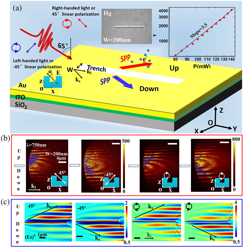
    Fig. 1. (a) Schematic diagram of the polarization-controlled SPP directional coupler. The PEEM image of the rectangular 20μm×0.2  μm trench is illuminated by a mercury lamp source (one-photon photoemission), and a double-logarithmic plot of the integrated photoemission signal versus the laser power yielding a slope of 3.5 in a linear fitting, is shown in the inset of (a). (b) PEEM images of SPPs launching with a 750 nm femtosecond laser under different polarization states. The black dotted frame shows the position of the trench. (c) Near-field distributions (EZ)2 of the SPP directional coupler (the rectangular 10μm×0.2  μm trench) following irradiation with different polarization states (+45° polarized and 45° polarized; right- and left-handed circularly polarized). The wave vectors of the incident light in-plane (kl) and SPP (ks) are displayed in (a). kl is directed toward +y. α is the polarization angle of the incident light.
    (a) Optimized temporal evolution of SPP near field at S1. (b) Interference field distribution of the incident light and SPP field recorded following irradiation with two perpendicular polarization directions (45° polarized and −45° polarized). (c) TR-PEEM experimental schematic illustration of the incident light with two polarization states perpendicular to the long axis of the trench. (d) The optimized PEEM images of SPPs launching using the 750 nm femtosecond laser with 45° polarized and −45° polarized. (e) Cross-sectional profiles of the interference pattern from the green dotted line in (d) obtained by subtracting the PE signal background.
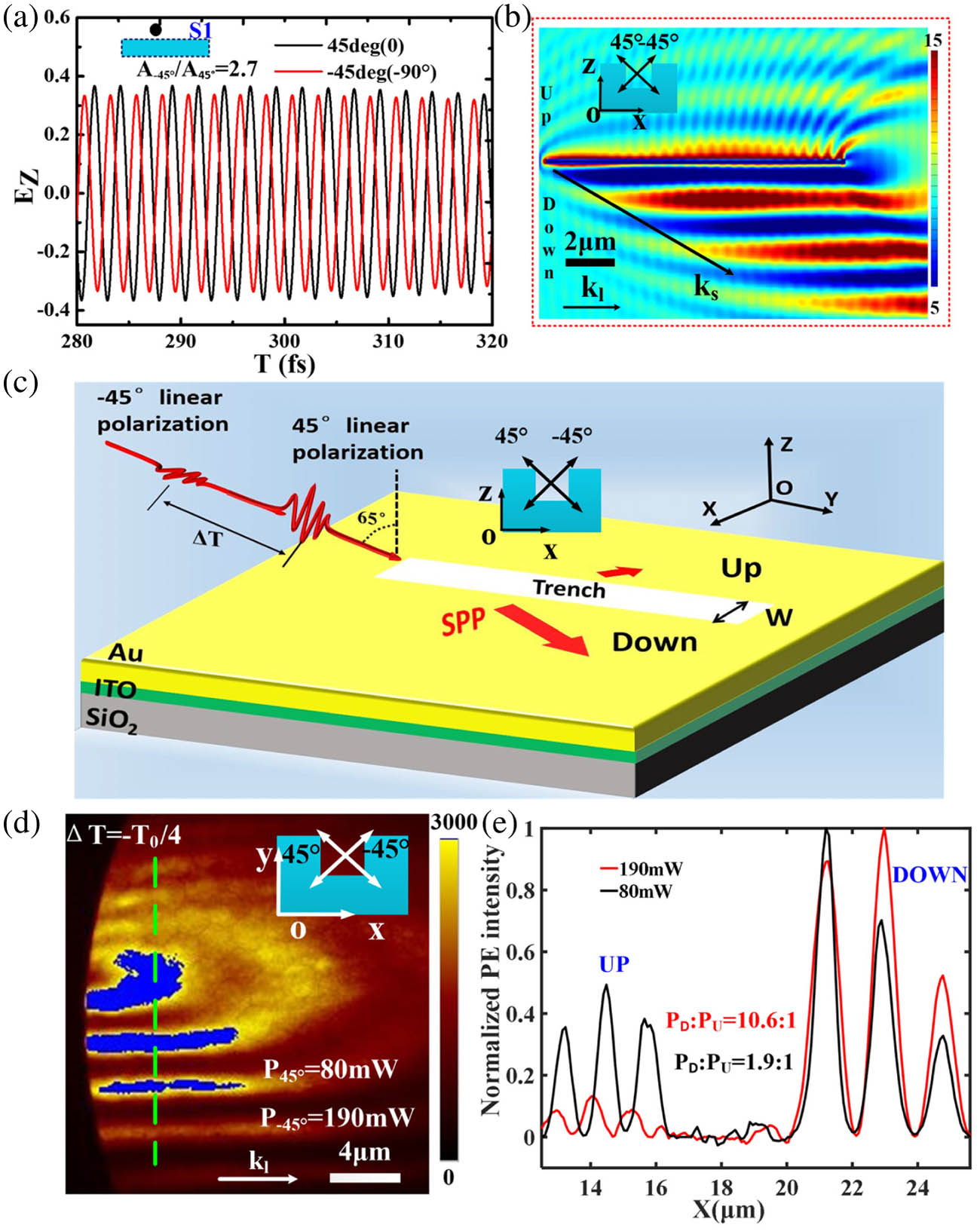
    Fig. 2. (a) Optimized temporal evolution of SPP near field at S1. (b) Interference field distribution of the incident light and SPP field recorded following irradiation with two perpendicular polarization directions (45° polarized and 45° polarized). (c) TR-PEEM experimental schematic illustration of the incident light with two polarization states perpendicular to the long axis of the trench. (d) The optimized PEEM images of SPPs launching using the 750 nm femtosecond laser with 45° polarized and 45° polarized. (e) Cross-sectional profiles of the interference pattern from the green dotted line in (d) obtained by subtracting the PE signal background.
    (a) Time-resolved PEEM images under different time delays captured using two 0° polarized and 90° polarized pulses. (b) Simulated temporal evolution of the SPP near field at positions S1 and S2 and (c) the instantaneous near-field distribution of the SPP directional coupler at different moments. The vector diagram of the instantaneous polarization direction of the incident light is at the bottom in (c). The blue shaded area represents the time range of SPP excitation by the overlapped region of the two laser pulses. Positions S1 (black dot) and S2 (red dot) are symmetrical about the trench, as shown in (c). The black dotted frame in (a) shows the position of the trench.
    Fig. 3. (a) Time-resolved PEEM images under different time delays captured using two 0° polarized and 90° polarized pulses. (b) Simulated temporal evolution of the SPP near field at positions S1 and S2 and (c) the instantaneous near-field distribution of the SPP directional coupler at different moments. The vector diagram of the instantaneous polarization direction of the incident light is at the bottom in (c). The blue shaded area represents the time range of SPP excitation by the overlapped region of the two laser pulses. Positions S1 (black dot) and S2 (red dot) are symmetrical about the trench, as shown in (c). The black dotted frame in (a) shows the position of the trench.
    (a) Time-resolved PEEM images under different time delays captured with two perpendicular polarization pulses (45° polarized and −45° polarized). (b) Simulated temporal evolution of the SPP near field at positions S1 and S2 and (c) the instantaneous near-field distribution of the SPP directional coupler at different moments. The vector diagram of the instantaneous polarization state of the incident light is at the bottom in (c). The blue shaded area represents the time range of the SPP excitation by the overlapped region of the two laser pulses. Positions S1 and S2 are symmetrical about the trench as shown in (c). The black dotted frame in (a) shows the position of the trench.
    Fig. 4. (a) Time-resolved PEEM images under different time delays captured with two perpendicular polarization pulses (45° polarized and 45° polarized). (b) Simulated temporal evolution of the SPP near field at positions S1 and S2 and (c) the instantaneous near-field distribution of the SPP directional coupler at different moments. The vector diagram of the instantaneous polarization state of the incident light is at the bottom in (c). The blue shaded area represents the time range of the SPP excitation by the overlapped region of the two laser pulses. Positions S1 and S2 are symmetrical about the trench as shown in (c). The black dotted frame in (a) shows the position of the trench.
    Yulu Qin, Boyu Ji, Xiaowei Song, Jingquan Lin. Ultrafast spatiotemporal control of directional launching of surface plasmon polaritons in a plasmonic nano coupler[J]. Photonics Research, 2021, 9(4): 514
    Download Citation