
Yulu Qin, Boyu Ji, Xiaowei Song, Jingquan Lin. Ultrafast spatiotemporal control of directional launching of surface plasmon polaritons in a plasmonic nano coupler[J]. Photonics Research, 2021, 9(4): 514
- Photonics Research
- Vol. 9, Issue 4, 514 (2021)
Abstract
1. INTRODUCTION
The remarkable performance of a plasmonic functional element has unique prospects for building high-speed, miniaturized signal processing systems [1]. In this regard, active control of the directional launch of surface plasmon polaritons (SPPs) is a key step for the construction of various plasmonic functional elements, such as switches [1–4], beam splitters [5], multiplexers [5–7], and waveguides [1,8,9].
As the main candidate for engineering control of SPP directional launching in plasmonic nanocircuits, the polarization-controlled scheme can easily achieve asymmetric momentum matching conditions between the incident light and the SPP along with different directions in the coupler [9–11]. This scheme has been used to implement active control of SPP propagation in diverse coupled structures, including carefully designed nanoparticle chains [12], branched silver nanowires [13], the plasmonic Y-splitter [7,14], single trench structures [9,10,15,16], the complementary split-ring resonators milled into thin metal film [17], and multilayered metal–dielectric–metal Huygens’ nanoantennas [18]. Among these structures, a single nano trench etched on a noble metal thin film supports broadband coupling, is compatible with planar technology [19], and meets the needs of device miniaturization [20]. Those features of the trench have aroused great interest among researchers.
Despite the above-mentioned progress, there are still many challenges to achieve active control of directional launching of SPPs to satisfy practical applications. On the one hand, all of the above approaches to the construction of an SPP directional coupler rely on the careful selection of the geometrical parameters of the coupled structure [12–18]. Previous theoretical work confirmed that directional launching of an SPP near field on a gold film by a circularly polarized dipole, and the extinction ratio of SPP propagation, both on gold film, can be optimized by adjusting the polarization of the elliptically polarized dipole [9]. However, there is a lack of experimental work with active schemes to substantially optimize the extinction ratio of an SPP directional launcher, except for changing the geometry structure, as reported in Refs. [3,21]. In fact, this is urgently needed in many practical plasmonic elements, such as plasmonic beam splitters [5,22] and switches [1,9,10]. On the other hand, with the increasing importance of ultrafast speed data processing and transport, it is foreseeable that ultrafast spatiotemporal control of directional launching of SPPs in plasmonic nanodevices is essential. Applications include ultrafast on–off of plasmonic switching and ultrafast information recording. The spatiotemporal control of localized surface plasmons in V-shaped [23] and solar-shaped [24] nanostructures has been realized using femtosecond pulses with chirp and polarization shaping, respectively. However, in terms of the directional launching of SPP, previous research has typically only focused on manipulation of the spatial field distribution, and there is a lack of ultrafast switching of the directional launching of the SPP [7–11].
Sign up for Photonics Research TOC. Get the latest issue of Photonics Research delivered right to you!Sign up now
In this paper, we are, to the best of our knowledge, the first to achieve ultrafast spatiotemporal control of the preferential launch direction of SPP on the nano-femtosecond (nano-femto) scale via a directional nano coupler (a single nano trench etched into a gold thin film) and confirmed using time-resolved photoemission electron microscopy (TR-PEEM). Our results show that preferential launching of an SPP directional coupler can be achieved by using destructive and constructive interference of the SPP modes excited by two orthogonally polarized incident light pulses. The extinction ratios of the SPP directional coupler can be substantially optimized by appropriately choosing the amplitude and initial phase of the incident light pulses. Furthermore, we demonstrate a solution for the preferential launch direction of SPP coupler switching on the femtosecond time scale by adjusting the time delay of the two orthogonally polarized incident light pulses. This result is attributed to the instantaneous change of the incident light polarization state at the femtosecond time scale. The TR-PEEM images are supported by finite-difference time-domain (FDTD) simulations. We believe the results of this study can be used to construct ultrafast information processing systems in plasmonic nanocircuits.
2. METHODS
3. RESULTS AND DISCUSSION
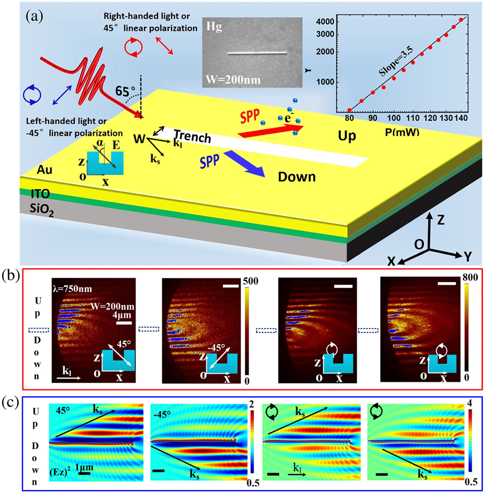
Figure 1.(a) Schematic diagram of the polarization-controlled SPP directional coupler. The PEEM image of the rectangular
Figure 1(b) shows the PEEM images after irradiation with linear ( polarized and polarized) and circular polarization (right- and left-handed circularly polarized) femtosecond pulses (, 1.6 eV) on the trench. The systematic simulation results show that when the incident light wavelength is 750 nm and the width of the trench is 200 nm, the SPP coupler (the trench) has optimal directivity when excited by circularly polarized light (not shown). An interference pattern is induced by the interaction of the incident femtosecond laser with the laser-induced SPP. This result suggests that the SPP field has good coherence with the incident light’s electric field under the experimental conditions, indicating the SPP near field is excited by resonance and its resonance frequency overlaps the incident laser light spectrum. Asymmetric photoemission distributions can be observed for the different polarizations. Specifically, the interference patterns mainly appeared on the upper side of the trench under 45° linear polarization or right-handed circular polarization, and correspondingly, the extinction ratio and 0.53, respectively, indicating SPP is preferentially excited on the upper side of the trench. Inversely, when the polarization angle is or for left-handed circular polarization, the intensity ratio of the PEEM images is about 1.2 and 1.4, respectively (i.e., the preferential launch direction of the SPP shift to the underside of the trench). Note that due to strong localized surface plasmon resonance, extremely bright hot spots appeared on the trench edges and corners during laser illumination, and those hotspots will easily cause CCD saturation and affect the observation of the relatively weak SPP field [15]. Therefore, for clear presentation of the propagation of SPPs, we removed the trench from the PEEM field of view. The black dotted frame in Fig. 1(b)indicates the position of the trench. The extinction ratio of the directional coupler is extracted by integrating the photoemission (PE) signal and subtracting the PE signal background generated by the incident light in the PEEM image.
Figure 1(c) shows the near-field distributions of the SPP directional coupler following irradiation under corresponding polarization conditions. Conventional photoemission experiments show that the measured multiphoton signal is predominantly governed by the component of the near field. The extinction ratios of and linear polarization (right and left-handed circular polarization) are reciprocal to each other, and are equal to 0.24 and 4.1 (0.63 and 1.59), respectively. The results show that the preferentially directional launch of the simulated SPP is consistent with the experimental results under the excitation conditions.
Further FDTD simulation results (not shown) indicate that the polarization dependence of the extinction ratios of the SPP coupler can be attributed to destructive and constructive interference of SPP modes excited by the two orthogonally polarized incident light pulses as the linearly and circularly polarized light beam can be decomposed into the superposition of two orthogonal components. Specifically, when the two SPP modes excited by the two orthogonally polarized incident light pulses are superimposed, constructive interference occurs on the upper side (or underside) of the trench and destructive interference occurs on the underside (or upper side) of the trench; this results in the SPP being preferentially excited on one side of the trench. Furthermore, the extinction ratios of the SPP directional coupler can be improved by appropriately adjusting the amplitude ratio of the two incident laser pulses.
![]()
Figure 2.(a) Optimized temporal evolution of SPP near field at S1. (b) Interference field distribution of the incident light and SPP field recorded following irradiation with two perpendicular polarization directions (45° polarized and
An experimental configuration for actively optimizing the extinction ratio of the SPP directional coupler is displayed in Fig. 2(c). Here, the femtosecond laser pulse is split into a pump-probe pulse pair; the time delay could be controlled by a Mach–Zehnder interferometer setup, where the 45° and polarized directions could be obtained by rotating a half-wave plate. Figure 2(d) displays the optimized PEEM image of the time delay (corresponds to a phase delay of ) using the excitation of 45° polarized and polarized pulses. The average power is 80 mW and 190 mW (the ratio is about 2.4) for the 45° polarized and polarized femtosecond pulses (, 1.6 eV) on the trench, respectively. Cross-sectional profiles of the interference patterns before and after optimization from the green dotted line in Fig. 2(d) are obtained by subtracting the PE signal background. It is found that the average intensity ratio of the photoemission signal of the SPP directional coupler is optimized from 1.9:1 to 10.6:1, as shown in Fig. 2(e). Here, and refer to the average intensity of the photoemission signal on the lower and upper sides of the SPP directional coupler, respectively.
We have demonstrated that the launch direction of SPP on the trench strongly depends on the polarization state of the incident light pulses. Based on this, it is foreseeable that manipulation of the instantaneous polarization state of the incident light at the femtosecond time scale will ultimately realize active control of the directional launch of SPP at the nano-femto scale.
![]()
Figure 3.(a) Time-resolved PEEM images under different time delays captured using two 0° polarized and 90° polarized pulses. (b) Simulated temporal evolution of the SPP near field at positions S1 and S2 and (c) the instantaneous near-field distribution of the SPP directional coupler at different moments. The vector diagram of the instantaneous polarization direction of the incident light is at the bottom in (c). The blue shaded area represents the time range of SPP excitation by the overlapped region of the two laser pulses. Positions S1 (black dot) and S2 (red dot) are symmetrical about the trench, as shown in (c). The black dotted frame in (a) shows the position of the trench.
This phenomenon is attributed to the change in the polarization state of the incident light and under the time delay above, the corresponding incident light polarization state after superposition is , 45°, and . Similarly, the preferential launch direction of the SPP switching phenomenon can also be found when the time delay is and (delay time is 130 fs and 131.25 fs). Nevertheless, the superposition of p polarized and s polarized light transforms incident light to a complex instantaneous polarization state under the time delays above. Therefore, the PEEM images are the result of integration following irradiation with a complex instantaneous polarization state. The ultrafast switching process of SPP preferential launch direction contained therein will be revealed by the numerical simulation below. At a time delay longer than 80T, the switching phenomenon of the SPP preferential launch direction almost disappeared because the p polarized and s polarized pulses are completely separated in time and only the photoemission signal of the PEEM image is induced by the p polarized and s polarized beams independently. These results demonstrate that the preferential launch direction of the SPP on the trench can be actively controlled with femtosecond accuracy (1.25 fs) by adjusting the time delay of the p polarized and the s polarized beams.
Figure 3(b) displays the simulated temporal evolution of SPP near field at positions S1 and S2 following irradiation with incident light with 0° (p) polarized and 90° (s) polarized pulses and the time delay of (delay time is 130 fs). In the entire evolution process, the intensity of SPP near field at position S1 is greater than or equal to that of the near field at S2, which results in an integrated photoemission electron signal intensity on the upper side of the trench that is greater than that of the underside, as shown in Fig. 3(a). To more intuitively present the instantaneous change of the preferential launch direction of the SPP on the trench, we simulated three typical instantaneous near-field distributions of the SPP directional coupler at , 330 fs, and 480 fs, respectively, in Fig. 3(c). We found that when and , the SPP launched on both sides of the trench is symmetrically distributed. When , it is in the overlapping area of two incident light pulses in time, and the preferential launch direction of the SPP is the upper side of the trench.
The above phenomenon can be explained by the instantaneous change in the polarization direction of the incident light field at the femtosecond time scale or by the interaction of the SPP fields induced by the p polarized and s polarized laser pulses [27,28]. Specifically, when the incident light irradiates the trench, the process of the SPP launched by the laser pulses can be divided into three parts, as shown in Fig. 3(b): (i) the SPP near field is excited by the first half of the first laser pulse and the corresponding time range is about 0–200 fs; (ii) the overlapping part of the two beams of light is converted to the SPP near field, which corresponds to the time range roughly from 200 to 480 fs; and (iii) the second half of the second laser pulse into the SPP near field with the time after 480 fs. Parts (i) and (iii) correspond to p and s polarized light, respectively, wherein the SPP near-field intensity is symmetrically distributed on both sides of the trench. Due to the different intensities of the two femtosecond laser pulses in the overlap period (ii) indicated by the blue shaded area in Fig. 3(b), the polarization direction of the incident light in (ii) changes between 0° and 90° based on the principle of electric field superposition. Previous studies have shown that the SPP near field is preferentially excited on the upper side of the trench [11,15] when the excitation laser polarization direction is between 0° and 90°. As a result, the integrated photoemission electron signal intensity on the upper side of the trench is larger than that of the underside, as shown in Fig. 3(a), when the time delay of the two beams is , showing that the preferential launch direction of the SPP is on the upper side of the trench. Vector diagrams of the instantaneous polarization state of the incident light corresponding to the three parts of the ultrafast SPP field evolution are displayed at the bottom of Fig. 3(c). The results above show that during the entire electric field evolution process (at the hundreds of femtosecond scale), the SPP near field on the underside of the trench undergoes an ultrafast process of on–off–on, while there is always SPP excited on the upper side of the trench.
![]()
Figure 4.(a) Time-resolved PEEM images under different time delays captured with two perpendicular polarization pulses (45° polarized and
Figure 4(b) shows the temporal evolution of the SPP near field at positions S1 and S2 following irradiation with the incident light with 45° polarized and polarized pulses and a time delay (130.63 fs). The blue shaded area represents the time range of SPP excitation by the overlapped region of the two laser pulses. For instance, before , the intensity of the SPP near field is suppressed at position S2 and it is smaller than the electric field at S1. After , the intensity of the SPP near field at position S2 is larger than at S1. The intuitively instantaneous near-field distribution of the SPP directional coupler at , 300 fs, and 430 fs is displayed, respectively, in Fig. 4(c). Different from Fig. 3(b), the SPP near fields that are excited on both sides of the trench are distributed asymmetrically during the entire evolution process; for , the preferential launch direction switches from the upper to the lower side of the trench. The significant difference in the instantaneous distribution of the SPP near field in Figs. 4(c) and 3(c) stems from the fact that the incident light has completely different instantaneous polarization states under the two excitation schemes. The results show that ultrafast switching (about 130 fs) of the preferential direction of the SPP launched from the upper side of the trench to the underside can be achieved. The vector diagram of the instantaneous polarization state of the incident light is shown at the bottom of Fig. 4(c). We believe the results above provide a solution for switching the preferential launch direction of the SPP by the coupler at the femtosecond time scale.
4. CONCLUSION
In summary, we performed spatiotemporal control of the preferential launch direction of an SPP directional coupler at a nano-femto scale using TR-PEEM schemes. We demonstrated a solution to switch the preferential launch direction of the SPP by the coupler at the femtosecond time scale by adjusting the time delay of the two orthogonally polarized incident light pulses. We believe this study can be used to develop high-speed, miniaturized signal processing systems.
Acknowledgment
Acknowledgment. The authors thank the Key Laboratory for Cross-Scale Micro and Nano Manufacturing (Ministry of Education), Changchun University of Science and Technology.
References
[1] D. K. Gramotnev, S. I. Bozhevolnyi. Plasmonics beyond the diffraction limit. Nature Photonics, 4, 83-91(2010).
[2] J. Jin, X. Li, Y. Guo, M. Pu, P. Gao, X. Ma, X. Luo. Polarization-controlled unidirectional excitation of surface plasmon polaritons utilizing catenary apertures. Nanoscale, 11, 3952-3957(2019).
[3] A. Pors, M. G. Nielsen, T. Bernardin, J. Weeber, S. I. Bozhevolnyi. Efficient unidirectional polarization-controlled excitation of surface plasmon polaritons. Light Sci. Appl., 3, e197(2014).
[4] J. Lin, J. P. B. Mueller, Q. Wang, G. Yuan, N. Antoniou, X. Yuan, F. Capasso. Polarization-controlled tunable directional coupling of surface plasmon polaritons. Science, 340, 331-334(2013).
[5] A. G. Joly, Y. Gong, P. Z. El-Khoury, W. P. Hess. Surface plasmon-based pulse splitter and polarization multiplexer. J. Phys. Chem. Lett., 9, 6164-6168(2018).
[6] A. Sumimura, M. Ota, K. Nakayama, M. Ito, Y. Ishii, M. Fukuda. Low-return-loss plasmonic multiplexer with tapered structure. IEEE Photon. Technol. Lett., 28, 2419-2422(2016).
[7] G. Razinskas, D. Kilbane, P. Melchior, P. Geisler, E. Krauss, S. Mathias, B. Hecht, M. Aeschlimann. Normal-incidence PEEM imaging of propagating modes in a plasmonic nanocircuit. Nano Lett., 16, 6832-6837(2016).
[8] S. I. Bozhevolnyi, V. S. Volkov, E. Devaux, J. Laluet, T. W. Ebbesen. Channel plasmon subwavelength waveguide components including interferometers and ring resonators. Nature, 440, 508-511(2006).
[9] F. J. Rodríguez-Fortuño, G. Marino, P. Ginzburg, D. O’Connor, A. Martínez, G. A. Wurtz, A. V. Zayats. Near-field interference for the unidirectional excitation of electromagnetic guided modes. Science, 340, 328-330(2013).
[10] S. Wang, C. Zhao, X. Li. Dynamical manipulation of surface plasmon polaritons. Appl. Sci., 9, 3297(2019).
[11] Y. Gong, A. G. Joly, P. Z. El-Khoury, W. P. Hess. Polarization-directed surface plasmon polariton launching. J. Phys. Chem. Lett., 8, 49-54(2016).
[12] M. Sukharev, T. Seideman. Phase and polarization control as a route to plasmonic nanodevices. Nano Lett., 6, 715-719(2006).
[13] Y. Fang, Z. Li, Y. Huang, S. Zhang, P. Nordlander, N. J. Halas, H. Xu. Branched silver nanowires as controllable plasmon routers. Nano Lett., 10, 1950-1954(2010).
[14] C. Rewitz, G. Razinskas, P. Geisler, E. Krauss, S. Goetz, M. Pawłowska, B. Hecht, T. Brixner. Coherent control of plasmon propagation in a nanocircuit. Phys. Rev. Appl., 1, 014007(2014).
[15] Y. Qin, X. Song, B. Ji, Y. Xu, J. Lin. Demonstrating a two-dimensional-tunable surface plasmon polariton dispersion element using photoemission electron microscopy. Opt. Lett., 44, 2935-2938(2019).
[16] Y. Qin, B. Ji, X. Song, J. Lin. Disclosing transverse spin angular momentum of surface plasmon polaritons through independent spatiotemporal imaging of its in-plane and out-of-plane electric field components. Photon. Res., 8, 1042-1048(2020).
[17] Y. Hwang, J. K. Yang. Directional coupling of surface plasmon polaritons at complementary split-ring resonators. Sci. Rep., 9, 7348(2019).
[18] S. Zeng, Q. Zhang, X. Zhang, X. Liu, J. Xiao. Unidirectional excitation of plasmonic waves via a multilayered metal-dielectric-metal Huygens’ nanoantenna. Opt. Lett., 43, 3053-3056(2018).
[19] S. I. Bozhevolnyi, V. S. Volkov, E. Devaux, T. W. Ebbesen. Channel plasmon-polariton guiding by subwavelength metal grooves. Phys. Rev. Lett., 95, 046802(2005).
[20] J. Yang, X. Xiao, C. Hu, W. Zhang, S. Zhou, J. Zhang. Broadband surface plasmon polariton directional coupling via asymmetric optical slot nanoantenna pair. Nano Lett., 14, 704-709(2014).
[21] W. Yao, S. Liu, H. Liao, Z. Li, C. Sun, J. Chen, Q. Gong. Efficient directional excitation of surface plasmons by a single-element nanoantenna. Nano Lett., 15, 3115-3121(2015).
[22] J. Liu, R. Pala, F. Afshinmanesh, W. Cai, M. L. Brongersma. A submicron plasmonic dichroic splitter. Nat. Commun., 2, 525(2011).
[23] M. I. Stockman, S. V. Faleev, D. J. Bergman. Coherent control of femtosecond energy localization in nanosystems. Phys. Rev. Lett., 88, 067402(2002).
[24] M. Aeschlimann, M. Bauer, D. Bayer, T. Brixner, S. Cunovic, F. Dimler, A. Fischer, W. Pfeiffer, M. Rohmer, C. Schneider, F. Steeb, C. Strüber, D. Voronine. Spatiotemporal control of nanooptical excitations. Proc. Natl. Acad. Sci. USA, 107, 5329-5333(2010).
[25] L. Zhang, A. Kubo, L. Wang, H. Petek, T. Seideman. Imaging of surface plasmon polariton fields excited at a nanometer-scale slit. Phys. Rev. B, 84, 245442(2011).
[26] P. B. Johnson, R. W. Christy. Optical constants of the noble metals. Phys. Rev. B, 6, 4370-4379(1972).
[27] A. Kubo, K. Onda, H. Petek, Z. Sun, Y. S. Jung, H. K. Kim. Femtosecond imaging of surface plasmon dynamics in a nanostructured silver film. Nano Lett., 5, 1123-1127(2005).
[28] P. Melchior, D. Bayer, C. Schneider, A. Fischer, M. Rohmer, W. Pfeiffer, M. Aeschlimann. Optical near-field interference in the excitation of a bowtie nanoantenna. Phys. Rev. B, 83, 235407(2011).

Set citation alerts for the article
Please enter your email address
© Copyright 2018-2021 | Chinese Laser Press. All Rights Reserved 沪ICP备15018463号-20