• Acta Optica Sinica
  • Vol. 39, Issue 4, 0406004 (2019)
Yuefeng Qi1、2、*, Qi Feng1、*, Jin Zhang1, Xin Zhang1, Mingjun Wang1, Dongsheng Tian3, and Wei Li4
Author Affiliations
  • 1 School of Information Science and Engineering, Yanshan University, Qinhuangdao, Hebei 0 66004, China
  • 2 Key Laboratory for Special Fiber and Fiber Sensor of Hebei Province, Qinhuangdao, Hebei 0 66004, China
  • 3 Key Laboratory for Microstructural Material Physics of Hebei Province, School of Science, Yanshan University, Qinhuangdao, Hebei 0 66004, China
  • 4 China Electronic Engineering Design Institute Co. Ltd., Beijing 100142, China
  • show less
    DOI: 10.3788/AOS201939.0406004 Cite this Article Set citation alerts
    Yuefeng Qi, Qi Feng, Jin Zhang, Xin Zhang, Mingjun Wang, Dongsheng Tian, Wei Li. Design of Fiber-Optic Current Transformer Based on Passive Phase Modulator[J]. Acta Optica Sinica, 2019, 39(4): 0406004 Copy Citation Text show less
    Structural diagram of FOCT with passive phase modulator
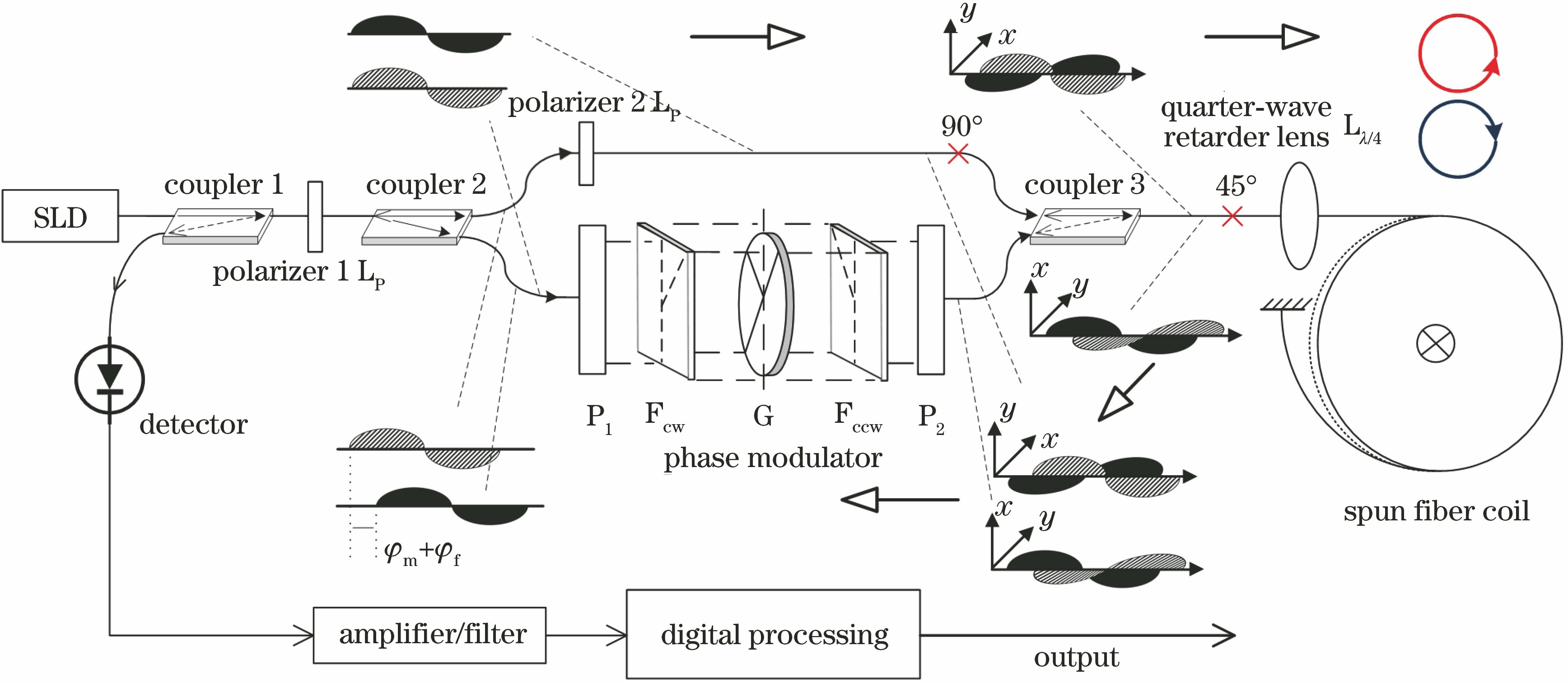
    Fig. 1. Structural diagram of FOCT with passive phase modulator
    Structural diagram of non-reciprocal passive phase modulator
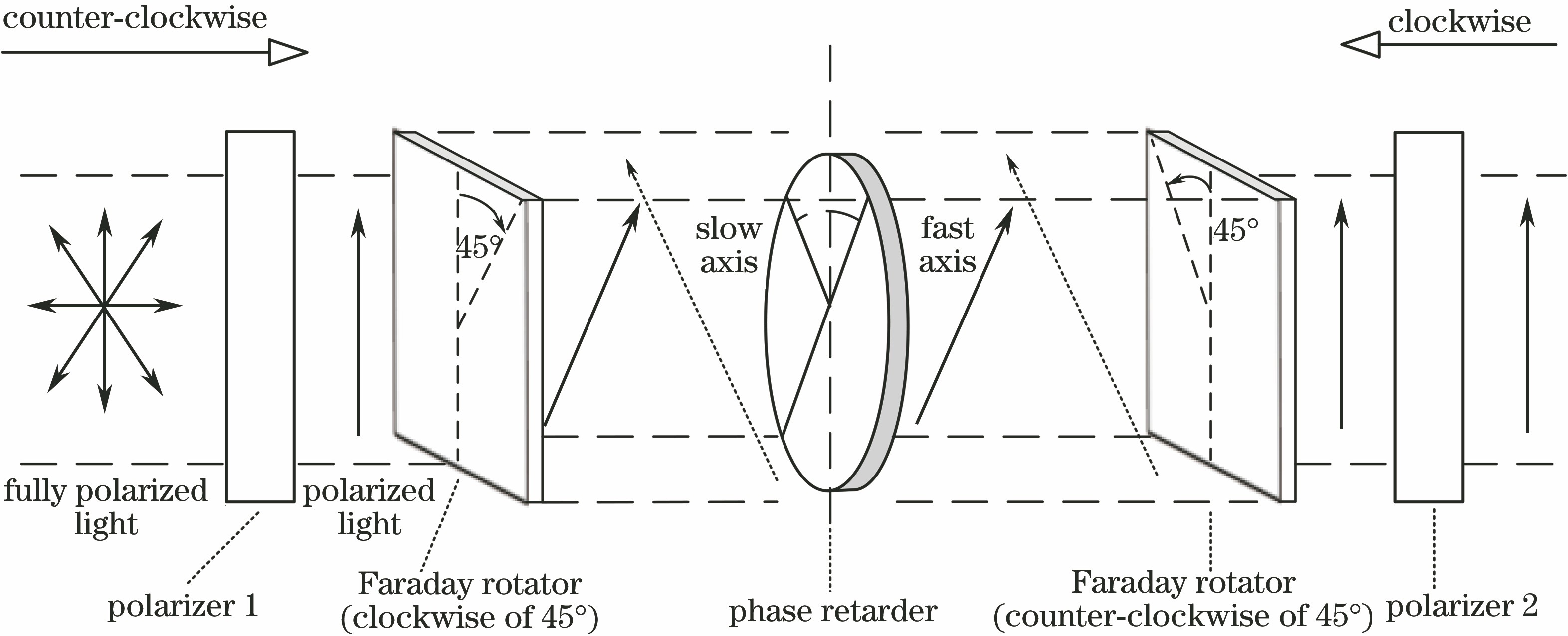
    Fig. 2. Structural diagram of non-reciprocal passive phase modulator
    Structural diagram of Jones matrix of FOCT
    Fig. 3. Structural diagram of Jones matrix of FOCT
    Effect of phase offset on output waveform. (a) Without phase offset; (b) with phase offset in counterclockwise direction; (c) with phase offset in clockwise direction
    Fig. 4. Effect of phase offset on output waveform. (a) Without phase offset; (b) with phase offset in counterclockwise direction; (c) with phase offset in clockwise direction
    Scheme for phase detection
    Fig. 5. Scheme for phase detection
    Analysis chart of system variation error. (a) Compound zero-order wave plate & Faraday rotators with different temperature characteristics; (b) true zero-order wave plate & Faraday rotators with different temperature characteristics; (c) multiple-order wave plate & Faraday rotators with different temperature characteristics
    Fig. 6. Analysis chart of system variation error. (a) Compound zero-order wave plate & Faraday rotators with different temperature characteristics; (b) true zero-order wave plate & Faraday rotators with different temperature characteristics; (c) multiple-order wave plate & Faraday rotators with different temperature characteristics
    Effect of temperature on system output response and phase offset. (a) Variations of output phase of phase modulator and detection light intensity; (b) variations of system change ratio error and phase output error
    Fig. 7. Effect of temperature on system output response and phase offset. (a) Variations of output phase of phase modulator and detection light intensity; (b) variations of system change ratio error and phase output error
    Temperature varying coefficient of Faraday rotator /[(°)∙℃-1]Compensation angle range (0.5 S) /(°)Compensation angle range (0.2 S) /(°)Corresponding wave plate initial phase delay range (optimal solution) /(°)Minimum ratio error /%
    0.02(-0.36,23.76)(7.74,17.1)(90.83,94.16)(-0.02,0.02)
    0.04(0.45,11.52)(4.50,8.28)(90.28,90.94)(-0.07,0.07)
    0.06(0.99,7.47)(3.60,4.86)(90.18,90.32)(-0.14,0.14)
    0.09(1.62,3.96)can not meet(90.04,90.22)(-0.31,0.31)
    Table 1. Angle parameters (compound zero-order wave plate)
    Yuefeng Qi, Qi Feng, Jin Zhang, Xin Zhang, Mingjun Wang, Dongsheng Tian, Wei Li. Design of Fiber-Optic Current Transformer Based on Passive Phase Modulator[J]. Acta Optica Sinica, 2019, 39(4): 0406004
    Download Citation