• Chinese Journal of Lasers
  • Vol. 47, Issue 12, 1206001 (2020)
Chen Yong1、*, Wu Jie1, Liu Huanlin2, and Zheng Han1
Author Affiliations
  • 1Key Laboratory of Industrial Internet of Things & Network Control, Ministry of Education, Chongqing University of Posts and Telecommunications, Chongqing 400065, China
  • 2Key Laboratory of Optical Fiber Communication Technology, Chongqing University of Posts and Telecommunications, Chongqing 400065, China
  • show less
    DOI: 10.3788/CJL202047.1206001 Cite this Article Set citation alerts
    Chen Yong, Wu Jie, Liu Huanlin, Zheng Han. Visible Light and Inertial Navigation Fusion Indoor Positioning System Based on Hidden Markov Model[J]. Chinese Journal of Lasers, 2020, 47(12): 1206001 Copy Citation Text show less

    Abstract

    Aiming at the problems of high mobile positioning complexity, low positioning accuracy, and unreasonable positioning for users in large indoor places, a visible light and inertial navigation fusion positioning algorithm based on the hidden Markov model is proposed in this work. First, the indoor parking lot map and positioning fingerprint in the off-line database construction stage are established, the visible light receiving signal strength of each reference node and the distance and angle between the nodes are collected, and a hidden Markov model is established. Then, in the online positioning stage, the candidate set of state transfer is reduced according to the user''s maximum moving speed, and the visible light signal and motion information are obtained. Finally, an improved Viterbi algorithm is used for user trajectory matching and positioning. Simulation results show that the proposed algorithm can accurately predict the user''s trajectory in an indoor parking lot of 2500m 2, the prediction accuracy of the reference node is about 85%, and the average positioning error is about 3.35 m. Compared with other four positioning algorithms, the positioning trajectory of the proposed algorithm is more continuous and smooth with higher accuracy.

    OCIS code 060.4510; 350.4600

    1 引言

    统计发现,人类超过一半的活动是在室内进行,诸如图书馆、医院、超市和地下停车场等大型室内场所,因此室内定位导航服务需求日益增多[1]。目前全球定位系统和北斗定位系统等主要应用于室外定位,卫星信号传播途中会被建筑物干扰,导致卫星信号变弱,无法实现室内定位。现今,室内定位技术普遍基于无线通信,例如Wi-Fi、蓝牙、射频识别等,无线信号在室内环境中易受到电磁干扰,导致定位精度降低,同时设备能耗较高,有一定的局限性[2-3]

    可见光通信(VLC)作为一种新兴的定位技术成为研究热点[4-6]。在室内定位中,多径干扰和障碍物遮挡等因素使接收信号不准确,降低了定位精度[7];Xu等[8]利用可见光接收信号强度进行指纹的定位,该方法需要在离线阶段采集指纹,当环境发生改变和接收信号不准确时,定位误差较大;对此,赵楚韩等[9]提出了一种改进的可见光指纹定位法(VLCFM),提高了室内定位精度,但对于面积较大的定位场景,随着距离的增大定位精度容易受到影响,且指纹过多会造成区分度较低;刘春燕[10]提出改进惯性导航定位算法(INPM),提高了行人室内定位的精度,当定位场景面积较小时,累积误差不可避免;李新春和王欢[11]提出一种基于稀疏指纹采集和改进加权K最近邻(weighted K-nearest neighbor,WKNN)的定位算法,解决了位置指纹定位算法中指纹采集工作量大、定位精度低的问题;Li等[12]使用粒子滤波器作为融合定位算法,对可见光与惯导技术进行融合;粒子滤波融合定位与卡尔曼滤波的方法类似,但是其精度更高,该方法的缺点是需要加入地图匹配来限制不合理的粒子;Zhu等[13]将算法与地图匹配进行融合,利用空间信息解决了定位的不合理性,但地图匹配计算复杂,造价昂贵,不适用于普遍使用。

    针对上述存在的问题,将隐马尔可夫模型(HMM)作为定位模型[14],并将可见光定位技术与惯性导航定位技术进行融合,实现室内停车场移动用户定位。在离线建库阶段,建立室内停车场地图和定位指纹图,采集每个参考节点的可见光接收信号强度、节点间的距离与角度信息,建立隐马尔可夫模型;在在线定位阶段,根据用户最大移动速度减小状态转移候选集,利用获取的可见光信号和运动信息并采用改进的维特比算法进行用户轨迹匹配定位。

    2 融合定位模型的建立

    大型场所的定位和导航是紧密相关的,需要利用系统所建立的地图让用户清晰地知道自己的位置和想要到达的地方。为此,图1中以停车场为例,以采集可见光接收信号强度(VLC-RSS)为基础并结合惯导数据,建立隐马尔可夫模型的室内指纹地图,图1中可到达区域和不可到达区域是分开的,所有标志处都对应一个参考节点,其覆盖的区域为有效区域,每个参考节点的指纹为

    S=L,I,RRSS,(1)

    式中:L为节点在真实环境的二维位置点;I为该节点的空间信息,如车位号、出入口、电梯号等; RRSS为可见光接收信号强度。

    每个参考节点之间的距离 D和角度 θ分别为

    D=diji,jS,1i,jN,(2)

    θ=θiji,jS,1i,jN,(3)

    式中: dij为节点i到节点j的距离; θij为节点i到节点j的角度;S为隐藏节点集合;N为所有节点的数量;ij为自然数。

    传统的指纹定位方法的复杂度较高,且较难实现对大型场所中用户的移动定位,对此本文提出采用HMM在有效定位区域布置参考节点方式。根据HMM的原理,其定位遵循两个规律:1)任意时刻的隐藏状态只依赖于前一时刻,即每个时刻定位节点之间转移的可能性就是状态转移概率;2)任意时刻的观测状态只依赖当前时刻的隐藏状态。图2是以图1为对象建立的HMM示意图,其中: S为隐藏状态,即系统中的定位点; O为观测状态,即系统可以接收的VLC和运动信息; PSt|St-1(t为时间)为转移概率,表示每个时刻定位点之间的转移可能性; POt|St表示用户在某个参考定位点接收到信号的概率。

    Indoor positioning fingerprint map

    Figure 1.Indoor positioning fingerprint map

    Diagram of HMM

    Figure 2.Diagram of HMM

    3 融合定位算法的设计

    3.1 离线阶段的建库

    在离线阶段,根据室内指纹地图建立定位模型,将定位参考节点作为隐藏状态 O,将VLC接收信号和运动信息作为观测状态 V,由状态转移概率组成状态转移矩阵 A,状态转移概率表示一个状态转换到另一个状态的可能性。根据已经测量好的距离矩阵和角度矩阵,再加上惯导模块测得的位移和角度变化,建立节点 i到其余所有节点的概率矩阵。从状态 Si转移到 Sj的转移概率定义为

    P1SiSj,m= 12πσmexp -m-dij22σm2,(4)

    P2SiSj,θt= 12πσθexp -θt-hij22σθ2,(5)

    式中: SiSj分别为节点 ij的状态; m为位移; dij为节点之间的距离; σm为测量位移的平均误差; θt为角度; hij为航向角; σθ为测量角度的平均误差。

    状态发射概率组成发射矩阵 B,它表示每一个隐藏状态都对应着一个观测状态,定位系统的发射概率表示为

    P(R|Si)= 12πσixx=1qexp -(rx-fix)22σix2,(6)

    式中: R为实时测量的指纹信息; σix为节点i处的标准接收信号强度偏差; q为AP数量; fixrx分别是参考指纹和实时指纹; x为AP编号。

    初始概率分布π就是定位开始阶段用户所处位置的概率分布,定位算法中所有节点的初始概率都选为1。

    3.2 候选集的选择

    在隐马尔可夫模型中进行参考节点的预测时通常采用维特比算法[15]。传统的维特比算法是在每个采样时间根据转移概率和发射概率匹配概率最大的路径作为定位结果,其复杂度为 ON2Kn,其中, N为参考节点数量, Kn为采样时间,复杂度过高且候选集过多会影响定位精度。对此,将用户最大移动速度引入状态转移矩阵,设定用户的最大移动速度为 V,采样间隔为 π,将二者相乘得到最大移动距离 M,M为半径画一个圆,该圆则是用户从 t时刻到 t+1时刻可能到达的范围,将圆内的参考节点 QtQt+1作为候选节点,圆以外的节点则为无效节点,无需对其进行候选匹配,如图3所示。此时状态转移概率矩阵的维度从 n×n降到 k×l(其中, k为采样时刻,l为当前节点的候选集数量),计算复杂度得到降低。

    Diagram of candidate set of user maximum speed limit

    Figure 3.Diagram of candidate set of user maximum speed limit

    3.3 在线定位阶段的轨迹匹配

    在在线定位阶段,根据 ABπ并利用用户携带的接收器和惯导模块采集观测数据,采用改进的维特比算法建立预测定位轨迹:

    δtj=maxδt-1i·PA·PB,(7)

    式中: δtj为前向概率; δt-1i为上一时刻参考节点概率; PA为状态转移概率; PB为发射概率。用户轨迹匹配定位步骤如下。

    t=1时,用节点的初始概率和发射概率的乘积作为前向概率,即

    δ1i=πi·PRtSi,(8)

    式中: δ1it=1时刻在 i节点的前向概率; πi为节点 i的初始概率; PRtSi为发射概率,与VLC接收信号强度相关; Rt为当前时刻测量的指纹信息。

    t>1时,节点 i的概率为上一时刻 t-1位置处的前向概率乘以状态转移概率和发射概率:

    δt(j)=maxδt-1i·P1SiSj,m·P2SiSj,θ·PRtSj(9)

    将上述4个概率相乘,概率最大的一个节点即为 t时刻的定位结果。

    经对维特比算法进行分析,并对比图4(a)、(b)可得,用户最大速度下候选集数量得到降低,维特比算法复杂度从 ON2Kn降为 OK1Kn,这为提高定位精度提供了依据。

    Schematic diagrams of Viterbi algorithm based on user maximum speed. (a) Traditional Viterbi algorithm; (b) improved Viterbi algorithm

    Figure 4.Schematic diagrams of Viterbi algorithm based on user maximum speed. (a) Traditional Viterbi algorithm; (b) improved Viterbi algorithm

    3.4 算法流程的设计

    图5为根据上述分析所设计的融合定位算法流程:在离线阶段,建立室内停车场地图,包含停车位、出入口、电梯等标志,然后将定位点加入到地图中,设立定位指纹图,指纹包含可见光接收信号信息和惯性导航信息,并建立各参考节点间的距离矩阵和角度矩阵,计算每个参考节点的发射矩阵和节点间的状态转移矩阵;在在线定位阶段,根据用户的最大移动速度确定候选集数量,根据采样时间内用户接收到的VLC信号强度和惯导模块接收到的角度与位移,计算用户状态转移概率和发射概率,在维特比解码器中求得的概率最大的节点即为定位点。

    Flow chart of fusion positioning algorithm

    Figure 5.Flow chart of fusion positioning algorithm

    4 仿真与结果分析

    4.1 仿真环境与条件

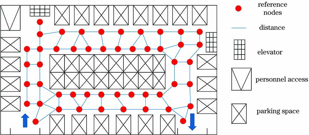
    为了评估本文定位算法对大型室内场所用户移动定位的效果,对某高校内一个室内停车场进行仿真。停车场长度为100m,宽为25m,总面积约为2500m2,停车场包括3个出入口、2条车道、82个停车位、1个供电房、2个楼梯和4个电梯。

    在离线建库阶段,建立HMM的参考节点(共162个节点),并测量每个节点之间的距离矩阵 D和角度矩阵 θ室内停车场所建立的HMM指纹地图如图6所示,仿真参数由表1所示。

    Fingerprint map of indoor parking lot

    Figure 6.Fingerprint map of indoor parking lot

    SymbolParameterValue
    SRoom size /m22500
    HPDReceiving height /m1
    HLEDLED height /m4
    NLedNumber of LEDs in each lamp26
    PPtTransmitted power of lamp /W5-10
    TTs(Ψ)Gain of optical filter1
    gΨGain of optical concentrator1
    FFOVField-of-view /(°)55
    APhysical area of photo-detector /cm21
    NnodesNumber of nodes162
    VmaxMaximum speed /(m·s-1)5

    Table 1. Simulation parameters

    4.2 仿真效果与分析

    根据停车场内的道路情况,结合行人和车辆用户的移动速度,设置用户的最大移动速度为5m·s-1,采样频率为1Hz,每次模拟用户移动5min,总共采集30条路径轨迹,轨迹长度范围为200~700m。图7为在室内停车场进行实验得到的轨迹图,图8为经过仿真得到的30次运动定位误差累积分布函数(CDF)。

    Experimental trajectory of indoor parking lot

    Figure 7.Experimental trajectory of indoor parking lot

    Cumulative error distribution function

    Figure 8.Cumulative error distribution function

    表2给出了30次运动实验的定位误差统计。测试3000~9000个节点(次),节点准确率约为85%,最大定位误差为5.5m,最大均方根误差为4.42m,最小定位误差为0.2m,最小均方根误差为3.95m,平均定位误差约为3.6m。3m以内的定位误差主要是来自网格内的随机移动和参考节点之间的距离差,3m以上的定位误差来源于节点转移判断错误。通过分析可知,所提算法可以满足用户在室内停车场实现移动定位的需求。

    Number of experimentsForecast numberof nodesAccuracy of nodeprediction /%Maximumerror /mMinimumerror /mAverageerror /mRoot meansquare error /m
    103000825.10.63.854.42
    206000855.40.33.473.95
    309000845.50.23.564.17

    Table 2. Positioning error statistics

    4.3 算法对比实验

    为了验证本文算法的优越性,选择可见光指纹定位(VLCFM)[9]、传统HMM可见光定位(VLC-HMM)、惯性导航定位(INPM)[10]和基于卡尔曼滤波的可见光与惯导融合定位(KF VLC-IN)[11]4种室内定位对比算法,其仿真结果如图9所示。

    Positioning track maps of four contrast algorithms. (a) Kalman filter based VLC and PDR fusion location trajectory map; (b) visible light fingerprint positioning trajectory; (c) traditional HMM VLC positioning trajectory; (d) inertial navigation positioning trajectory

    Figure 9.Positioning track maps of four contrast algorithms. (a) Kalman filter based VLC and PDR fusion location trajectory map; (b) visible light fingerprint positioning trajectory; (c) traditional HMM VLC positioning trajectory; (d) inertial navigation positioning trajectory

    图10给出了所提算法与4种定位算法的定位误差累积分布函数图。分析可知:1)基于卡尔曼滤波的VLC-PDR(Pedestrian Dead Reckoning)融合定位得到的92%的定位误差在6m以内,其缺点是每一时刻都要利用两种定位方法同时采集数据并同时进行算法融合,复杂度较高,在停车场的边缘和角落处的定位精度不高,如图9(a)所示;2)VLC指纹定位法的定位轨迹不连续[图9(b)],因噪声引起定位点的偏移,95%的定位误差在7m以内;3)将可见光信号作为观测量的传统HMM定位方法的误差较大,其主要原因是观测量太少,VLC信号不稳定很容易造成预测点偏移 [图9(c)],并影响后续的节点预测,其96%的定位误差在7m以内,该方法还存在候选节点太多的问题;4)惯性导航定位的轨迹一开始比较准确,随着时间的推移,累计误差越来越大,轨迹也随之发生偏移,如图9(d)所示;5)本文算法(图10)得到的95%的定位误差在5m以内,其平均定位误差相比其他对比算法更小,定位更加连续且接近真实运动轨迹,如图7所示。为直观地体现本文算法的优越性,表3列出所提算法与对比算法的各项指标,可以看出,本文方法的整体指标优于4种对比算法。

    CDF of positioning error of compared algorithms

    Figure 10.CDF of positioning error of compared algorithms

    PositioningmethodMaximumerror /mMinimumerror /mAverageerror /mRoot meansquare error /mMedianerror /m
    VLCFM[9]7.30.104.615.104.22
    VLC-HMM7.40.305.526.135.04
    INPM[10]9.60.056.627.145.56
    KF VLC-IN[11]6.50.604.274.853.74
    Proposed method5.50.203.353.882.92

    Table 3. Positioning error statistics of compared algorithms

    4.4 用户最大速度下候选集的确定

    根据3.2节所提方法,以图6的场景为例设定其移动速度为0.1~5.0m·s-1,所对应的候选节点数量为1~8。通过仿真分析候选节点数量对定位误差的影响。图11为不同候选节点数量对应的定位误差,可以看出,随着候选集数量的增加,定位误差减小。在开始阶段,定位误差随着候选节点数量的增加而急剧下降,这是因为增加候选节点的数量将扩大寻找最佳路径的搜索区域。当候选节点的数量达到特定值时,即当最大移动速度为4m·s-1、候选集为6个节点时,搜索范围已经覆盖了所有可能的搜索区域,定位误差将降为最小。若继续增加节点,搜索范围会超出搜索区域,导致误差的增加。

    Location error graph corresponding to different numbers of candidate nodes

    Figure 11.Location error graph corresponding to different numbers of candidate nodes

    5 结论

    选取隐马尔可夫模型作为定位模型,设计可见光与惯导融合定位算法。在离线阶段建立室内停车场指纹图,采集可见光信号和运动信息。在在线定位阶段,根据用户的最大移动速度减少候选集数量,从而提高定位速度;设计改进的维特比算法用于预测用户的运动轨迹。仿真结果表明,所提算法能准确连续地预测用户运动轨迹,并且其定位复杂度较低。与其他几种定位算法相比,所提算法在大型室内场所的移动定位误差更低,为大型室内场所的定位与导航提供参考。

    References

    [1] Tao Y, Zhao L. A novel system for WiFi radio map automatic adaptation and indoor positioning[J]. IEEE Transactions on Vehicular Technology, 67, 10683-10692(2018). http://ieeexplore.ieee.org/document/8445663

    [2] Zhou M, Liu Y Y, Wang Y et al. Anonymous crowdsourcing-based WLAN indoor localization[J]. Digital Communications and Networks, 5, 226-236(2019).

    [3] Jia B, Huang B Q, Gao H P et al. Selecting critical WiFi APs for indoor localization based on a theoretical error analysis[J]. IEEE Access, 7, 36312-36321(2019).

    [4] Zhang J, Wang H. An improved SNR uniformity optimization scheme for VLC system[J]. Journal of Chongqing University of Posts and Telecommunications (Natural Science Edition), 27, 78-82(2015).

    [5] Khan L U. Visible light communication: applications, architecture, standardization and research challenges[J]. Digital Communications and Networks, 3, 78-88(2017).

    [6] Liu H Y, Ma J H, Huang Q. Construction method of fingerprint database based on improved Kriging interpolation for indoor location[J]. Journal of Chongqing University of Posts and Telecommunications (Natural Science Edition), 29, 751-757(2017).

    [7] Chen Y, Li Y C, Liu H L. Moving target positioning method based on visible light communication in time division multiplexing network[J]. Chinese Journal of Lasers, 44, 1006003(2017).

    [8] Xu S W, Wu Y, Su G D. Fingerprint matchingand localization algorithm based on orthogonal frequency division multiplexing modulation for visible light communication[J]. Laser & Optoelectronics Progress, 56, 090601(2019).

    [9] Zhao C H, Zhang H M, Song J. Fingerprint based visible light indoor localization method[J]. Chinese Journal of Lasers, 45, 0806002(2018).

    [10] Liu C Y. Indoor localization method based on pedestrian dead reckoning aided by multi-source fusion[J]. Journal of Chinese Inertial Technology, 24, 208-214(2016).

    [11] Li X C, Wang H. Fingerprint location using sparse fingerprint acquisition and improved WKNN[J]. Journal of Chongqing University of Posts and Telecommunications (Natural Science Edition), 31, 451-459(2019).

    [12] Li X C, Feng L H, Yang A Y. Fusion based on visible light positioning and inertial navigation using extended Kalman filters[J]. Sensors, 17, 1093-1099(2017).

    [13] Zhu N, Zhao H B, Feng W Q et al. A novel particle filter approach for indoor positioning by fusing WiFi and inertial sensors[J]. Chinese Journal of Aeronautics, 28, 1725-1734(2015).

    [14] Adams S, Beling P A, Cogill R. Feature selection for hidden Markov models and hidden semi-Markov models[J]. IEEE Access, 4, 1642-1657(2016). http://ieeexplore.ieee.org/document/7450620

    [15] Liu C X, Lu G Q, Tang H B et al. Adaptive deployment method for virtualized network function based on viterbi algorithm[J]. Journal of Electronics & Information Technology, 38, 2922-2930(2016).

    Chen Yong, Wu Jie, Liu Huanlin, Zheng Han. Visible Light and Inertial Navigation Fusion Indoor Positioning System Based on Hidden Markov Model[J]. Chinese Journal of Lasers, 2020, 47(12): 1206001
    Download Citation