1Photonics Research Group, Department of Information Technology, Ghent University-IMEC, Ghent, Belgium
2Center for Nano- and Biophotonics (NB-photonics), Ghent University, Belgium
3State Key Laboratory for Modern Optical Instrumentation, Centre for Optical and Electromagnetic Research, Zhejiang Provincial Key Laboratory for Sensing Technologies, Zhejiang University, Hangzhou, China
Ang Li, Qiangsheng Huang, Wim Bogaerts, "Design of a single all-silicon ring resonator with a 150 nm free spectral range and a 100 nm tuning range around 1550 nm," Photonics Res. 4, 0084 (2016)
Copy Citation Text
We present a novel and simple method to obtain an ultrawide free spectral range (FSR) silicon ring resonator together with a tuning range covering the entire spectrum from 1500 to 1600 nm. A ring resonator with a large FSR together with a high Q factor, high tuning efficiency, and low fabrication cost and complexity is desired formany applications. In this paper, we introduce a novel way to make such a ring resonator, which takes advantage of the well-known resonance-splitting phenomenon. It is a single ring resonator with an FSR of more than 150 nm around 1550 nm and which has an easy thermo-optic tunability that can produce a tuning range around 90 nm or even more. Moreover, the device is simple to implement and can be fabricated in standard complementary metal-oxide semiconductor technology without requiring any kind of complicated processing or extra materials. The potential applications include single mode laser cavities, wavelength division multiplexing filters, (de)multiplexers, optical sensors, and integrated reflectors.
Microring resonators (MRRs) have proven to be one of the most intensively used components in various applications, covering laser cavities, wavelength division multiplexing filters, optical sensors, optical (de)multiplexers, all-optical signal processing, and more [1–6]. Silicon photonics is a very attractive platform to implement MRRs because of its high index contrast and compatibility with complementary metal oxide semiconductor (CMOS) technology [7,8]. This allows the fabrication of compact rings with small round-trip length, leading to a large free spectral range (FSR). Most applications desire a ring resonator with a large FSR, wide tuning range, low insertion loss, high quality factor, and narrow bandwidth (BW) as well as low fabrication cost and complexity. However, these performance indicators cannot all be optimized at the same time; there is always a trade-off. For instance, the most straightforward way to get a ring resonator with a large FSR is to shorten its length, as the FSR is inversely proportional to the round-trip length: , where is the resonance wavelength and and are the group index and total length of the ring waveguide, respectively.
But it is not possible to reduce the round-trip length of the ring indefinitely. First of all, this will complicate the tuning scheme. Moreover, a very short length means a very sharp bend radius, sometimes smaller than 5 mm in silicon strip waveguides. This can lead to significant bend loss as well as bend/straight transition loss [9,10] and make the ring more vulnerable to sidewall roughness as the mode profile in the bend waveguide is positioned closer to the outer wall. It is also difficult to obtain the correct coupling coefficient in the coupling sections because of the extremely short coupling length. All these factors impose a lower limit on the ring round-trip length and therefore an upper limit on the FSR.
Most applications limit the operational wavelength range of the ring to a single FSR. In silicon nanophotonic waveguides, the widest practical FSRs are of the order of 40 nm in the telecommunication C-band around 1550 nm [11], and the tuning efficiency is fixed at a value around 370 nm/RIU (refractive index unit), according to Eq. (1) [8], where are the resonance wavelength shift and the effective index change, respectively. This tuning efficiency generates a tuning range limited to 7 nm if the thermo-optic effect is applied, as the temperature variation induced by the heater is generally less than 100 K and the thermo-optic coefficient of silicon is [12]. A ring resonator that has a much wider FSR or is even free of any FSR, can be tuned in a much wider range by a simple thermo-optic effect, and at the same time does not suffer from implementation or performance limitations is therefore highly desirable:
Sign up for Photonics Research TOC. Get the latest issue of Photonics Research delivered right to you!Sign up now
Some work from other researchers has been done to implement ring resonators with a very wide FSR [11,13–16]. Apart from drastically reducing the bend radius, these methods can be classified in two categories: the use of the Vernier effect in multiple rings [15,16] and the use of intraring reflectors, which require complicated processing or CMOS-incompatible materials [13,14,17].
Multiple rings will impose additional requirements on the design accuracy and fabrication tolerance, as the resonance wavelength and BW of the individual rings need to be extremely well matched. Otherwise the multiring configuration can result in a split resonance. Beside, the tuning efficiency is relatively poor and the resonance mode is hard to move continuously in the spectrum; moreover, the well-known problem of backscattering induced splitting is not considered and cannot be compensated [18].
An alternative is to introduce reflectors into the ring to induce a strong coupling between the clockwise and the counterclockwise propagating modes. Bragg gratings can be used to implement this effect, but the need for high-resolution e-beam lithography negates some of the advantages of current silicon photonics technologies. The same can be said for the use of metal particles as a backreflector, which would introduce material incompatibilities. Moreover, Bragg gratings and metal particles are accompanied with extra loss, namely radiation loss and absorption loss. As clearly shown in [13], the factor as well as the extinction ratio of the resonance is quite poor. Again, these methods, even though they make use of deliberate backreflection, cannot compensate for unintentional, stochastic backscattering along the circumference of the ring.
Our device presented in this paper is a simple structure consisting of a ring resonator with a loop Mach–Zehnder interferometer (MZI) reflector inside the ring to intentionally introduce reflection. The device is accompanied with an ultrawide FSR that spans more than 150 nm. Beside, by implementing two phase shifters, which can be based on a simple thermo-optic effect, its tuning range can almost cover the whole spectrum from 1500 to 1600 nm; this is equivalent to a tuning efficiency 13 times higher than that of a normal silicon ring resonator. Moreover, for most of the former literature, the ring can only be configured as an all-pass ring; thus the applications are limited. The device proposed in this paper could be configured as either an all-pass or an add–drop ring resonator.
The paper is constructed in the following way: in Section 2 we will explain the schematic of the device as well as the theory behind this phenomenon by means of temporal coupled mode theory (tCMT). In Section 3, the design principles, detailed characterization, and simulation results using the circuit simulator Caphe [19] will be given. Finally we will conclude our work.
2. THEORY AND SCHEMATIC
In this section, we will first use tCMT to explain how reflection inside the MRR could significantly influence the extinction ratio of a resonance of an MRR. Here the extinction ratio is defined as , where is the power transmission at one resonance. Then we will introduce how to get an ultrawide FSR by taking advantage of this phenomenon. Finally we will give and briefly introduce the schematic of our device.
A. Extinction Ratio Modified by Reflection Inside the MRR
tCMT has been used intensively to analyze a ring resonator with or without reflection [18,20–22]. We will first use tCMT to build a model for an ideal MRR and then build a model for an MRR with reflection inside, to clearly and quantitatively show how the reflection will influence the performance (resonance wavelength, extinction ratio, etc.) of the ring.
1. tCMT for Ideal MRR
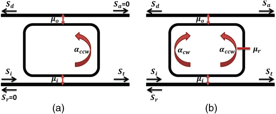
For an ideal MRR without any kind of reflection or backscattering inside, there is only one circulating mode when only one port is injected with light as shown in Fig. 1(a). According to tCMT, equations describing the circulating mode as well as the transmitted wave amplitude at throughport are given in Eqs. (2) and (3) [20,21]:
Figure 1.Schematic of the tCMT model for ring resonators. (a) In an ideal ring resonator with no reflection inside, only one circulating mode is activated. (b) In a ring resonator with internal backreflection, the two modes are coupled and thus simultaneously active.
Here, stands for the energy amplitude of the counterclockwise propagating mode, normalized such that represents the total stored energy of this mode in the ring. refers to the wave amplitude at each port, quite similar to the electric filed amplitude, as also has the unit of power. The decay rates and describe the transfer of energy to the input and output bus waveguides, and represents the intrinsic (“unloaded”) round-trip loss. The couplings in the directional couplers and are related to these decay rates and the field coupling coefficients and as in Eq. (4) [21]:
Here, are light speed in a vacuum, the group index of the waveguide, and the physical length of the ring, respectively. The term denotes the round-trip loss of the electric field in the MRR and is similar in concept with the field coupling coefficients and . After solving Eqs. (2) and (3), we can extract a straightforward formula for the amplitude as well as the power at each port as in Eqs. (5) and (6):
Clearly, the resonance is a Lorentzian-shape line. Its central frequency or wavelength is entirely determined by the physical length and effective index of the MRR. The extinction ratio is directly related with the transmission at the resonance frequency , which is shown in Eq. (7):
When , then , or physically speaking, when the power coupled into the MRR from the input port equals the round-trip loss plus the power coupled to the output port , we get critical coupling, which gives us the largest extinction ratio. For an all-pass ring, where , the critical coupling condition is changed to . It is in good correspondence with former literature which describes critical coupling in the space domain [8]. In [8], the critical coupling condition for an all-pass MRR gives the same result, while for an add–drop MRR it is written as . After some transformation we get , where the term is generally two orders of magnitudes smaller, and therefore negligible. At that point it becomes the same as our condition, which is .
2. tCMT Model for an MRR with Reflection Inside
After having an understanding of the tCMT and the concept of critical coupling, we will derive the equations for MRR with internal reflection. The essential difference with an ideal MRR is that, due to reflection inside, the two degenerate circulating modes (clockwise), and (counterclockwise) are coupled and activated simultaneously, as illustrated in Fig. 1(b). This leads to resonance splitting and a change in the extinction ratio. The equations for amplitudes of these modes are modified to Eqs. (8) and (9):
There is an extra term of appearing in these equations. Here we consider a simple coupling of these two modes, which means the coupling is conservative instead of dissipative. Similar to and , refers to the mutual coupling between these two modes. But it is slightly different in its dependency on the field reflectivity as given in Eq. (10):
The equation to get and remains the same as Eq. (3) (note that even though the equations are the same, are modified), but and are modified to Eq. (11). And this time, we get quite a different formula for as in Eq. (12):
Clearly, instead of one single Lorentzian-shape resonance as in Eq. (5), there are now two Lorentzian-shape resonances with their own resonance frequencies . The modified power transmission at the resonance frequencies or are given in Eq. (13). Note that in Eq. (13), , and are already replaced by Eqs. (4) and (10):
If , Eq. (13) becomes identical to Eq. (7). Because of the existence of reflection , the transmission at resonance becomes impossible to directly analyze in a quantitative way. By assuming the MRR is still at the original critical coupling point as an ideal MRR, we will see how the extinction ratio changes dramatically with the reflection. By making , is modified to Eq. (14):
In Fig. 2, we get the extinction ratio of a critically coupled MRR as a function of field reflectivity under different field coupling coefficients . Clearly, the extinction ratio drops dramatically with increasing reflectivity. This phenomenon is one of the basic principles in our paper to get an ultrawide FSR in an MRR. We will introduce a reflector whose reflection spectrum is strongly wavelength dependent. In a specific configuration, we can obtain a spectrum where only a single resonance suffers zero reflection while the others within a wavelength range of 150 nm suffer from strong reflection.
Figure 2.At the critical coupling point, the extinction ratio drops dramatically with increasing reflection until it reaches an almost constant value.
Before this, we investigate how the extinction ratio changes with reflectivity when the MRR is not critically coupled. This is important because in reality, it is very difficult to fabricate a ring where all coupling factors and losses are matched at the correct wavelength, due to fabrication variability. So exploring the behavior of the ring in the non-critical-coupling regime can also be considered as a fabrication tolerance analysis of the device. In Fig. 3 the dependency of extinction ratio on reflectivity under different coupling strengths is given. In contrast to Fig. 2, the MRR is not configured at the critical coupling point. The loss factor is set to be constant at 0.0114, corresponding with a 0.05 dB round-trip power loss, and is set to be identical with , which is often the case and much easier to ensure than an absolute coupling coefficient.
Figure 3.Extinction ratio still changes significantly with increasing reflectivity when the MRR is configured as , which is the general case and easy to guarantee.
It is natural to expect a performance degradation due to the deviation from the critical coupling condition, which appears in the smoother slope and the smaller side mode suppression ratio (SMSR); here SMSR is defined as , where refer to the extinction ratio of the resonance that suffers zero reflection and the resonance that suffers strong reflection, respectively. However, the extinction ratio still drops significantly with increasing reflectivity, and it is noteworthy that the extinction ratio of the remaining resonance () as well as the SMSR can be improved simply by increasing the coupling coefficient, as illustrated in Fig. 4. This device is then quite practical, as we require no exact configuration such as critical coupling. Another advantage is that in this configuration the MRR becomes less sensitive to stochastic backscattering, which we will discuss in detail in a later section.
Figure 4.These figures show how the extinction ratio as well as the side mode suppression changes with power coupling coefficient when the MRR is designed as . (a) Extinction ratio as a function of coupling coefficient. (b) Side mode expression as a function of coupling coefficient.
Now we get to know that the reflection will significantly reduce the extinction ratio of the resonance. If we could find a way to make all but one resonance of the ideal MRR suffer from strong reflection while the rest suffer zero reflection, then only one resonance has a large extinction ratio while all the rest have a very small extinction ratio, and we could consider this MRR as FSR free. This requirement could be achieved by introducing a tunable reflector consisting of a loop MZI, as shown in Fig. 5. This circuit can generate various reflection spectra based on the lengths of its two arms. Section 3 discusses the design and simulation in detail.
Figure 5.The ring resonator has a loop MZI tunable reflector inside, which introduces a wavelength-dependent intentional reflection that couples two circulating modes.
The schematic of the MRR with an ultrawide FSR is given in Fig. 5. It consists of an MRR with an embedded asymmetric MZI reflector, which intentionally introduces a wavelength-dependent reflection that couples the two circulating modes (CW and CCW).
3. DESIGN, SIMULATION, AND ANALYSIS
A. Design
The key design parameter of the loop-MZI reflector is the length difference between the two arms. The absolute length of each arm depends on the specific application. For instance, for sensing we prefer a longer arm to capture more particles; however, for filters or laser cavities, we would rather make them as short as possible to reduce the loss, footprint, and stochastic backscattering. The zero-reflection wavelength depends on the as in Eq. (15):
Here, is the interference order, similar to the parameter of a normal MZI. The simulated reflection spectra with various generated by the circuit simulator Caphe [19] is given in Fig. 6.
Figure 6.Curves of the reflection spectra of the reflector. The directional couplers are designed to be a 50/50 splitter. (a) The directional coupler performance is wavelength independent. (b) A linear model for directional coupler extracted from FDTD simulation is added.
In the simplified case where the directional coupler is treated as an ideal, wavelength-independent component, a larger will lead to a smaller FSR and a sharper slope. More interesting is the case where a realistic behavior of the directional coupler is applied, which is a linear wavelength dependency extracted from a finite-difference time-domain simulation. In that case the FSR seems to be independent of , while the slope still shows the same dependency on . This facilitates our design as we can now get a large FSR together with a sharp reflection slope.
B. Simulation
In Fig. 7, the simulated throughport spectrum of our device is plotted. Here, , ; thus , the total round-trip length is set to be around 150 mm, and a resonance appears at 1540 nm. The round-trip loss is set to be 0.05 dB (corresponding with a loss coefficient of 330 dB/m), and . Corresponding with the theory, only the resonance of zero reflection shows a large extinction ratio in the ring spectrum, while the other resonances have a very small extinction ratio and a clear resonance splitting. Besides, we notice that another part of the theory is also verified, which is that the SMSR and extinction ratio of the surviving resonance could be increased simply by coupling more power into the ring, as also shown in Fig. 7. Even though for large coupling coefficient, for instance, , the adjacent resonance modes start to arise, we can again suppress them by increasing the interference number as this will sharpen the slope of the reflector spectrum. This feature will be also mentioned and illustrated in Fig. 13 in Section 3.D. However, we need to bear in mind that by increasing the power coupling coefficient, the BW and the factor of the resonance will be broadened and decreased, respectively, which is not so desirable in many applications.
Figure 7.Simulated throughport of our device. The order is chosen to be 23, and the MRR is set at the normal coupling condition .
We also look into the tunability of the device. As our device consists of two components that can be individually tuned, namely, a ring resonator and an MZI based reflector, we can easily implement two very different tuning mechanisms or configurations by either tuning the whole device as discussed in Section 3.C.1 or separately tuning the ring and the reflector, as in Section 3.C.2.
1. Common Tuning
When the effective index of the waveguide changes on a global scale (e.g., by ambient temperature variations or background index change), both the zero-reflection wavelength as well as the resonance wavelength of the ring will drift at the same rate, as in Eq. (16). In Fig. 8, the spectra of both the tunable reflector and MRR at different global effective indices are given:
Figure 8.In common tuning configuration, the zero-reflection wavelength of the reflector and the resonance wavelength of the MRR shift at the same rate, and thus the MRR remains single mode. (a) The shift of the zero-reflection wavelength of the MZI based reflector induced by effective index neff change. (b) The shift of the resonance wavelength of the MRR induced by effective index neff change.
This configuration gives the same tuning efficiency and thus the same tuning range as a regular silicon ring resonator, which is not particularly efficient. However, if we direct our attention from tuning to sensing applications, this configuration could be quite promising, as no matter how large the background index changes are, the single mode condition remains within the ultrawide FSR and the resonance shifts corresponds with the background index change. In other words, this configuration could be very suitable for sensing applications, especially in a large and rapid index change environment.
2. Separate Tuning
Alternatively, we can tune the ring and the reflector separately. In Fig. 9 we add two phase shifters for one arm of the reflector and the ring waveguide, respectively. Logically speaking, the phase shifter 1 (PS1) performs the function of resonance selection. It selects one out of all the resonances of the ring to be the single mode of the device. The phase shifter 2 (PS2) takes the responsibility of comb tuning. It shifts the resonance spectrum of the ring resonator so that the single resonance selected by PS1 can be adjusted locally to cover a continuum rather than some discrete points. Mathematically speaking, the shift of the zero-reflection wavelength of the reflector is given in Eq. (17) and the shift of the resonance mode of the ring resonator is given in Eq. (18):
Figure 9.Instead of using one common phase shifter, we can implement two separate phase shifters to achieve individual tuning of the zero-reflection wavelength of the reflector and the resonance wavelength of the ring.
is the wavelength of the single resonance. At its original state, this is the zero-reflection wavelength of the reflector, and it matches one of the resonance wavelengths of the ring resonator.
and are the effective index change in PS1 and PS2, respectively. Similarly, refer to the length of these two phase shifters.
stands for the rest length of the ring resonator. equals the total length of ring .
and are the shift of the zero-reflection wavelength of the reflector and the resonance wavelength of the ring resonator, respectively.
In contrast to the common tuning configuration, where the zero-reflection wavelength of the reflector and the resonance wavelength of the ring resonator shift at the same rate as in Eq. (16), they now shift at a very different rate. The former one shifts much more efficiently, depending on the value of and . This provides the possibility to achieve a much wider tuning range. Specifically, when FSR, the new zero-reflection wavelength will again match one of the resonances of the ring resonator; thus the single mode condition remains. In the first design (where , , ), we achieve a higher tuning efficiency as illustrated in Fig. 10. In other words, with the same amount of effective index change (around 0.02), a tuning range of 30 nm is achieved instead of 7 nm. With further optimization (, , , and the same loss coefficient of 330 dB/m), the tuning range can expand to almost 100 nm, covering the spectrum from 1500 to 1600 nm, as illustrated in Fig. 11.
Figure 10.Two phase shifters are implemented, with PS1 responsible for the mode selection and PS2 in charge of comb tuning. With the same index change, we achieve a 4 times larger wavelength shift compared to common tuning. (a) Without PS2, the single mode resonance can only take place at some discrete wavelength points, as the zero-reflection wavelength of the reflector might not match the resonance of the ring. (b) With PS2 working, the single mode resonance can be tuned continuously, as the resonance of the ring resonator can now be aligned to the zero-reflection wavelength of the reflector.
Figure 11.When optimizing for a larger tuning range (at the cost of smaller SMSR) we achieve a tuning range almost as wide as 100 nm with the same index change.
In Fig. 12, we give a more straightforward way to illustrate how to tune the PS1 and PS2 in order to achieve a continuous tuning of the single mode wavelength. Clearly, by tuning the index change of PS1 and PS2 in a feasible range (0–0.02), we can address a continuous shift of the single mode wavelength in a 30 nm span or a 90 nm span, depending on the design parameters of the MZI reflector. And at each wavelength, an extinction ratio larger than 30 dB and a side mode suppression larger than 26 dB (14 dB for 90 nm tuning span) can be guaranteed. In other words, a wide tuning range comes at the price of a smaller side mode suppression. However, the extinction ratio would be roughly independent of the length of PS1. Thus, the choice between a larger tuning range and a larger side mode suppression would depend on its specific application. These figures actually reveal another important feature of our device, which is the tolerance to the design accuracy. In other words, it does not require a ridiculously precise design of the individual optical length, as the single mode condition can be always achieved by dynamic tuning PS1 and PS2.
Figure 12.Tuning maps for the two phase shifters PS1 and PS2 to achieve a continuous shift of the single mode resonance. (a), (c), and (e) give the results of the first design, where the SMSR of each wavelength is larger than 28 dB while the tuning range is only 30 nm, 4 times wider than that of a normal silicon ring resonator. The results of the modified design are illustrated in (b), (d), and (f) where the design parameters are changed to achieve a much wider tuning range around 90 nm at the price of a smaller SMSR, but still, at each wavelength, a SMSR larger than 14 dB can be guaranteed. (a) Wavelength of single mode ring 1. (b) Wavelength of single mode ring 2. (c) Extinction ratio of single mode ring 1. (d) Extinction ratio of single mode ring 2. (e) Side mode suppression of single mode ring 1. (f) Side mode suppression of single mode ring 2.
Now we need to focus on some more practical issues, for instance, the well-known backscattering in a silicon-on-insulator MRR. Backscattering can introduce power reflectivity in a single mode silicon strip waveguide with dimensions around [23]. As mentioned above, the total length of our MRR is very flexible and can be as short as 150 mm. The only drawback of the long length is its higher power reflection caused by the backscattering as it linearly scales with length.
In Fig. 13, we show the influence of backscattering for an MRR configured at the normal coupling condition (). As expected, the backscattering induced reflection will degrade the performance. When the length grows from 150 to 300 mm, and the power reflectivity caused by backscattering increases from 0.00105 to 0.0021, the single mode condition is damaged when the ring is configured at and . But still, one could increase the performance by simply coupling more light and increasing the resonant number , as illustrated in Figs. 13(b) and 13(c).
Figure 13.Effect of unintentional backscattering on the performance of the MRR. The SMSR decreases with increasing length and backscattering. But it could be compensated by increasing and .
In conclusion, in this paper, we proposed a novel and simple method to obtain an all-silicon ring resonator which has only a single resonance in a wavelength range of over 150 nm and a 13 times higher tuning efficiency compared to normal silicon ring resonator, that is to say, a tuning range almost as wide as 100 nm. One significant advantage is its simple structure, which is compatible with most of today’s CMOS-based silicon photonics technology platforms. We provide a comprehensive and systematic theoretical model based on tCMT. Simulations with respect to the main design parameters are discussed, as well as the tolerance to the well-known and unavoidable backscattering.
[16] D. Geuzebroek, E. Klein, H. Kelderman, F. Tan, D. Klunder, A. Driessen. Thermally tuneable, wide FSR switch based on micro-ring resonators. IEEE/LEOS Benelux Chapter 2002 Annual Symposium, 155-158(2002).
[18] A. Li, T. V. Vaerenbergh, P. De Heyn, Y. Xing, P. Bienstman, W. Bogaerts. Experimentally demonstrate the origin for asymmetric resonance splitting and contributions from couplers to backscattering in SOI microrings. Advanced Photonics, IM2B.6(2015).
Ang Li, Qiangsheng Huang, Wim Bogaerts, "Design of a single all-silicon ring resonator with a 150 nm free spectral range and a 100 nm tuning range around 1550 nm," Photonics Res. 4, 0084 (2016)