• Photonics Research
  • Vol. 9, Issue 5, 668 (2021)
Shiqiao Wu1、2, Bin Jiang1、2, Yang Liu1、2, and Jian-Hua Jiang1、2、3、*
Author Affiliations
  • 1School of Physical Science and Technology, Soochow University, Suzhou 215006, China
  • 2Collaborative Innovation Center of Suzhou Nano Science and Technology, Suzhou 215006, China
  • 3Key Lab of Advanced Optical Manufacturing Technologies of Jiangsu Province and Key Lab of Modern Optical Technologies of Ministry of Education of China, Soochow University, Suzhou 215006, China
  • show less
    DOI: 10.1364/PRJ.418689 Cite this Article Set citation alerts
    Shiqiao Wu, Bin Jiang, Yang Liu, Jian-Hua Jiang. All-dielectric photonic crystal with unconventional higher-order topology[J]. Photonics Research, 2021, 9(5): 668 Copy Citation Text show less
    (a) Schematic illustration of the 2D hexagonal PhC. Inset shows the zoom-in structure of the unit cell. Gray region is air, while the green dots denote the dielectric rods with a diameter D=4 mm and a relative permittivity εd=24. The lattice vectors of the hexagonal lattice, a→1 and a→2, are depicted. The lattice constant is a=25 mm, while the distance between the center of a rod and the unit cell center, d, is tunable. (b) Photonic band structure for d=0.47a. The photonic band gap (green region) has a nontrivial topological index of χ(6)=(0,−2). The little group representations (i.e., A, B, and E) are labeled on the band structure. The phase profiles for the electric field Ez of the corresponding Bloch states are shown in (c). (d) Evolutions of the first six bands at the high symmetry points, Γ, M, and K, with the geometry parameter d. (e) Evolutions of the bulk bands (frequency ranges) and the band gaps with the parameter d. (f) Evolutions of the first six bands at the high symmetry points, Γ, M, and K, with the relative permittivity εd. (g) Evolutions of the bulk bands (frequency ranges) and the band gaps with the relative permittivity εd.
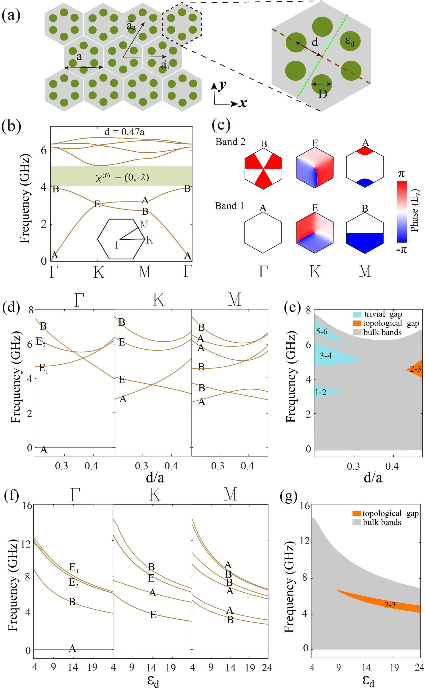
    Fig. 1. (a) Schematic illustration of the 2D hexagonal PhC. Inset shows the zoom-in structure of the unit cell. Gray region is air, while the green dots denote the dielectric rods with a diameter D=4  mm and a relative permittivity εd=24. The lattice vectors of the hexagonal lattice, a1 and a2, are depicted. The lattice constant is a=25  mm, while the distance between the center of a rod and the unit cell center, d, is tunable. (b) Photonic band structure for d=0.47a. The photonic band gap (green region) has a nontrivial topological index of χ(6)=(0,2). The little group representations (i.e., A, B, and E) are labeled on the band structure. The phase profiles for the electric field Ez of the corresponding Bloch states are shown in (c). (d) Evolutions of the first six bands at the high symmetry points, Γ, M, and K, with the geometry parameter d. (e) Evolutions of the bulk bands (frequency ranges) and the band gaps with the parameter d. (f) Evolutions of the first six bands at the high symmetry points, Γ, M, and K, with the relative permittivity εd. (g) Evolutions of the bulk bands (frequency ranges) and the band gaps with the relative permittivity εd.
    (a) Photonic dispersions at the bulk, edge, and corners. Both the bulk and edge dispersions are calculated using the structure illustrated in the upper panel of (b). The corner frequency is calculated from the finite structure illustrated in (c). Upper panel of (b): Structure for the study of the edge states, which is finite along the y direction but periodic in the x direction. PEC boundaries are imposed at the left and right ends of the structure. Lower panels of (b): Amplitude and phase profiles of the electric field Ez for the two edge states labeled by the stars in (a). (c) Illustration of the finite structure used to study the corner states. (d) Distribution of the summed electric field intensity for all the corner states. There are six degenerate corner states, as shown in Fig. 3(a). In all calculations, a thin layer of air with a width of 0.08a is set between the PEC boundary and the PhC.
    Fig. 2. (a) Photonic dispersions at the bulk, edge, and corners. Both the bulk and edge dispersions are calculated using the structure illustrated in the upper panel of (b). The corner frequency is calculated from the finite structure illustrated in (c). Upper panel of (b): Structure for the study of the edge states, which is finite along the y direction but periodic in the x direction. PEC boundaries are imposed at the left and right ends of the structure. Lower panels of (b): Amplitude and phase profiles of the electric field Ez for the two edge states labeled by the stars in (a). (c) Illustration of the finite structure used to study the corner states. (d) Distribution of the summed electric field intensity for all the corner states. There are six degenerate corner states, as shown in Fig. 3(a). In all calculations, a thin layer of air with a width of 0.08a is set between the PEC boundary and the PhC.
    (a) Photonic spectrum for the finite PhC structure illustrated in Fig. 2(c). Only the eigenstates in and around the bulk band gap are shown. (b) Spectral charges for various unit cells. The gray region denotes the bulk. The blue region denotes the edges, while the red region denotes the corners. (c) Local density-of-states (DOS) for photons in three different types of unit cells labeled by the triangle (corner unit cell), rectangle (edge unit cell), and the star (bulk unit cell). Integrating the photonic LDOS up to the frequency fgap=4 GHz gives rise to fractional spectral charges at the corner boundaries. (d) Illustration of the distribution of the fractional corner charges in a finite sample. In all calculations, a thin layer of air with the width 0.08a is set between the PEC boundary and the PhC.
    Fig. 3. (a) Photonic spectrum for the finite PhC structure illustrated in Fig. 2(c). Only the eigenstates in and around the bulk band gap are shown. (b) Spectral charges for various unit cells. The gray region denotes the bulk. The blue region denotes the edges, while the red region denotes the corners. (c) Local density-of-states (DOS) for photons in three different types of unit cells labeled by the triangle (corner unit cell), rectangle (edge unit cell), and the star (bulk unit cell). Integrating the photonic LDOS up to the frequency fgap=4  GHz gives rise to fractional spectral charges at the corner boundaries. (d) Illustration of the distribution of the fractional corner charges in a finite sample. In all calculations, a thin layer of air with the width 0.08a is set between the PEC boundary and the PhC.
    (a) Spectral charges for various unit cells in a finite disclination structure from the first-principle calculations. Integrating the calculated photonic LDOS up to the frequency fgap=4 GHz gives the spectral charges presented in the figure. (b) Spectrum of the photonic eigenstates for the finite-sized disclination structure. (c) The five localized states bound to the disclination core. In all calculations, a thin layer of air with the width 0.08a is set between the outside PEC boundary and the PhC and another layer of air with the width 0.03a is set between the inner PEC boundary and the PhC.
    Fig. 4. (a) Spectral charges for various unit cells in a finite disclination structure from the first-principle calculations. Integrating the calculated photonic LDOS up to the frequency fgap=4  GHz gives the spectral charges presented in the figure. (b) Spectrum of the photonic eigenstates for the finite-sized disclination structure. (c) The five localized states bound to the disclination core. In all calculations, a thin layer of air with the width 0.08a is set between the outside PEC boundary and the PhC and another layer of air with the width 0.03a is set between the inner PEC boundary and the PhC.
    (a) Wannier center distributions in the disclination structure for the trivial PhC with d/a=0.25. No fractional spectral charge is accumulated since the localized position of Wannier center is at the center of each unit cell. (b) Photonic spectrum of the disclination structure for the trivial PhC. There is no disclination state. Only bulk states are found. In all calculations, a thin layer of air with the width 0.08a is set between the outside PEC boundary and the PhC and another layer of air with the width 0.03a is set between the inner PEC boundary and the PhC.
    Fig. 5. (a) Wannier center distributions in the disclination structure for the trivial PhC with d/a=0.25. No fractional spectral charge is accumulated since the localized position of Wannier center is at the center of each unit cell. (b) Photonic spectrum of the disclination structure for the trivial PhC. There is no disclination state. Only bulk states are found. In all calculations, a thin layer of air with the width 0.08a is set between the outside PEC boundary and the PhC and another layer of air with the width 0.03a is set between the inner PEC boundary and the PhC.
    Frequency shift of the disclination and defect states when the disclination structure contains an additional dielectric rod near the disclination core. The location of the defect rod is indicated by the black, blue, and red dots in the insets. The radius of the defect pillar is 2 mm. We study the frequency shifts of the disclination and defect states as functions of the relative permittivity of defect rod. Frequency of disclination states (α,β, or γ) and defect state as functions of the relative permittivity of the dielectric rod for three different defects is summarized in (a)–(c) and (d), respectively.
    Fig. 6. Frequency shift of the disclination and defect states when the disclination structure contains an additional dielectric rod near the disclination core. The location of the defect rod is indicated by the black, blue, and red dots in the insets. The radius of the defect pillar is 2 mm. We study the frequency shifts of the disclination and defect states as functions of the relative permittivity of defect rod. Frequency of disclination states (α,β, or γ) and defect state as functions of the relative permittivity of the dielectric rod for three different defects is summarized in (a)–(c) and (d), respectively.
    Shiqiao Wu, Bin Jiang, Yang Liu, Jian-Hua Jiang. All-dielectric photonic crystal with unconventional higher-order topology[J]. Photonics Research, 2021, 9(5): 668
    Download Citation