• Photonics Research
  • Vol. 2, Issue 4, B54 (2014)
Kun Xu*, Ruixin Wang, Yitang Dai, Feifei Yin, Jianqiang Li, Yuefeng Ji, and and Jintong Lin
Author Affiliations
  • State Key Laboratory of Information Photonics & Optical Communications (Beijing University of Posts and Telecommunications), P.O. Box 55 (BUPT), Beijing 100876, China
  • show less
    DOI: 10.1364/PRJ.2.000B54 Cite this Article Set citation alerts
    Kun Xu, Ruixin Wang, Yitang Dai, Feifei Yin, Jianqiang Li, Yuefeng Ji, and Jintong Lin. Microwave photonics: radio-over-fiber links, systems, and applications [Invited][J]. Photonics Research, 2014, 2(4): B54 Copy Citation Text show less
    Fundamental setup of externally modulated RoF link.
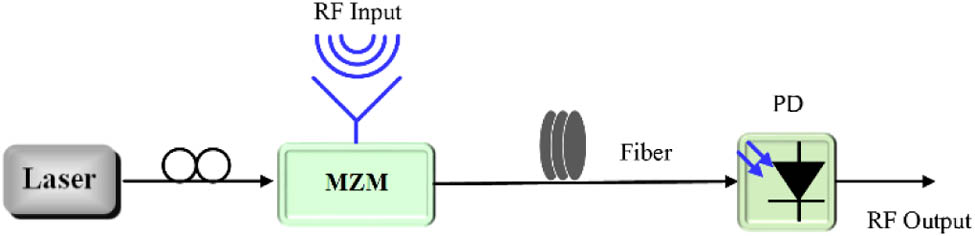
    Fig. 1. Fundamental setup of externally modulated RoF link.
    (a) Experimental arrangement for the IMD3 suppression in analog fiber-optic link employing OCB processing. Electrical spectra of the output fundamental signal and their IMD3s for (b) the conventional link without any processing in the optical domain and (c) the proposed link with OCB processing. (d) Two-tone measurement results for the compensated and uncompensated links. ESA, electrical spectrum analyzer.
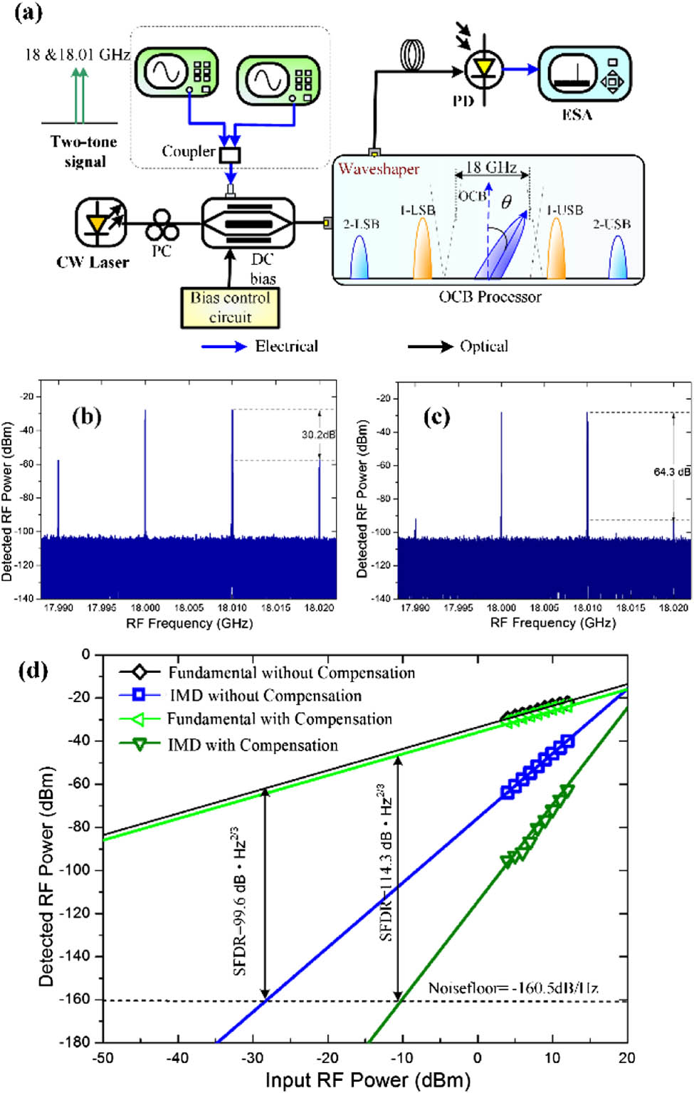
    Fig. 2. (a) Experimental arrangement for the IMD3 suppression in analog fiber-optic link employing OCB processing. Electrical spectra of the output fundamental signal and their IMD3s for (b) the conventional link without any processing in the optical domain and (c) the proposed link with OCB processing. (d) Two-tone measurement results for the compensated and uncompensated links. ESA, electrical spectrum analyzer.
    (a) Experimental setup of the proposed phase error correction system. BPF: bandpass filter. (b) RMS jitter of the remote RF signal without (blue line) and with (red line) phase error correction. (c) SSB phase noise of the RF source and signal at the remote end.
    Fig. 3. (a) Experimental setup of the proposed phase error correction system. BPF: bandpass filter. (b) RMS jitter of the remote RF signal without (blue line) and with (red line) phase error correction. (c) SSB phase noise of the RF source and signal at the remote end.
    Schematic of the system that combines broadband photonics and high-resolution electronics.
    Fig. 4. Schematic of the system that combines broadband photonics and high-resolution electronics.
    Configuration of the coherent OFC-based channelization scheme. PBS, polarization beam splitter; PBC, polarization beam coupler.
    Fig. 5. Configuration of the coherent OFC-based channelization scheme. PBS, polarization beam splitter; PBC, polarization beam coupler.
    Output of the first, fourth, and sixth channels when RF signals of 4.111, 5.55, and 6.63 GHz are inputted, respectively.
    Fig. 6. Output of the first, fourth, and sixth channels when RF signals of 4.111, 5.55, and 6.63 GHz are inputted, respectively.
    (a) Output of the fourth, fifth, and sixth channels when 6.055 GHz signal is inputted. (b) Normalized channel response of the third channel with center frequency of 5 GHz and channel width of 500 MHz.
    Fig. 7. (a) Output of the fourth, fifth, and sixth channels when 6.055 GHz signal is inputted. (b) Normalized channel response of the third channel with center frequency of 5 GHz and channel width of 500 MHz.
    (a) System configuration of the proposed scheme. (b) Spectrum of a single tone. (c) Spectrum of PRBS. * denotes convolution. (d) Spectrum of the encoded signal. The dashed green line indicates the frequency response of the LPF. (e) Enlargement of the LPF’s passband. The dashed red line denotes the case of inputting another RF tone. PPG, pulse pattern generator; AWG, arbitrary waveform generator.
    Fig. 8. (a) System configuration of the proposed scheme. (b) Spectrum of a single tone. (c) Spectrum of PRBS. * denotes convolution. (d) Spectrum of the encoded signal. The dashed green line indicates the frequency response of the LPF. (e) Enlargement of the LPF’s passband. The dashed red line denotes the case of inputting another RF tone. PPG, pulse pattern generator; AWG, arbitrary waveform generator.
    Experimental results. (a) Self-correlation function of p(f). (b) Input and recovered spectrum of a RF signal with 20 tones. (c) Input and recovered spectrum of a RF signal with 40 tones ranging from 0.1 to 1 GHz.
    Fig. 9. Experimental results. (a) Self-correlation function of p(f). (b) Input and recovered spectrum of a RF signal with 20 tones. (c) Input and recovered spectrum of a RF signal with 40 tones ranging from 0.1 to 1 GHz.
    (a) Schematic diagram of multiple LO generation, electro-optical mixing, and channelized heterodyne detection. (b) Illustration of multiband LO generation. (c) Illustration of signal multicasting and the instantaneous bandwidth.
    Fig. 10. (a) Schematic diagram of multiple LO generation, electro-optical mixing, and channelized heterodyne detection. (b) Illustration of multiband LO generation. (c) Illustration of signal multicasting and the instantaneous bandwidth.
    (a) Dual coherent OFCs with 18 GHz center frequency shift and 38 and 30 GHz mode spacing. (b) Channelized dual OFCs, with one carrying the signal. (c)–(f) Generated multiple LOs within different bands. (g)–(i) Multicast signals within different bands. (j) EVM test results of the multicast signals.
    Fig. 11. (a) Dual coherent OFCs with 18 GHz center frequency shift and 38 and 30 GHz mode spacing. (b) Channelized dual OFCs, with one carrying the signal. (c)–(f) Generated multiple LOs within different bands. (g)–(i) Multicast signals within different bands. (j) EVM test results of the multicast signals.
    Typical simulcast WLAN RoF DAS architecture.
    Fig. 12. Typical simulcast WLAN RoF DAS architecture.
    Comparison of fiber effect via different fiber delays between RAU-A and RAU-B. Solid lines represent basic access mode and dashed lines represent RTS/CTS exchange mode.
    Fig. 13. Comparison of fiber effect via different fiber delays between RAU-A and RAU-B. Solid lines represent basic access mode and dashed lines represent RTS/CTS exchange mode.
    (a) Normalized throughputs for the basic-access DCF mode, DCF in RTS/CTS mode, and adaptive PCF as a function of the number of RAUs assuming identical fiber length. (b) Throughput performance of each RAU as the function the length of one of the fiber links assuming different fiber lengths in a two-RAU scenario.
    Fig. 14. (a) Normalized throughputs for the basic-access DCF mode, DCF in RTS/CTS mode, and adaptive PCF as a function of the number of RAUs assuming identical fiber length. (b) Throughput performance of each RAU as the function the length of one of the fiber links assuming different fiber lengths in a two-RAU scenario.
    Conceptual architecture of multiband satellite repeater based on OFCs. LNA: low noise amplifier.
    Fig. 15. Conceptual architecture of multiband satellite repeater based on OFCs. LNA: low noise amplifier.
    Conceptual architecture of a next-generation intelligent wireless information system.
    Fig. 16. Conceptual architecture of a next-generation intelligent wireless information system.
    Kun Xu, Ruixin Wang, Yitang Dai, Feifei Yin, Jianqiang Li, Yuefeng Ji, and Jintong Lin. Microwave photonics: radio-over-fiber links, systems, and applications [Invited][J]. Photonics Research, 2014, 2(4): B54
    Download Citation