State Key Laboratory of Information Photonics & Optical Communications (Beijing University of Posts and Telecommunications), P.O. Box 55 (BUPT), Beijing 100876, China
Microwave photonics (MWPs) uses the strength of photonic techniques to generate, process, control, and distribute microwave signals, combining the advantages of microwaves and photonics. As one of the main topics of MWP, radio-over-fiber (RoF) links can provide features that are very difficult or even impossible to achieve with traditional technologies. Meanwhile, a considerable number of signal-processing subsystems have been carried out in the field of MWP as they are instrumental for the implementation of many functionalities. However, there are still several challenges in strengthening the performance of the technology to support systems and applications with more complex structures, multiple functionality, larger bandwidth, and larger processing capability. In this paper, we identify some of the notable challenges in MWP and review our recent work. Applications and future direction of research are also discussed.
Microwave photonics (MWPs) is an interdisciplinary field that studies the interaction between microwaves and lightwaves, combining in consequence the advantages brought by both areas [1–6]. In general, MWP uses the strength of photonic techniques to generate, distribute, process, and analyze microwave signals. Because of the inherent properties of photonics, such as low loss transmission, there has been an increasing effort to develop MWP techniques for different applications, including broadband wireless access networks [7], satellite communications [8], optical signal processing [9], electronic warfare systems [10], and optical coherence tomography techniques [11]. Many of these application areas demand ever-increasing values for speed, bandwidth, and dynamic range while at the same time requiring devices that feature small size, lightweight and low-power performance, large tenability, and strong immunity to electromagnetic interference.
Radio-over-fiber (RoF) is one of the main topics of MWP, providing features that are very difficult or even impossible to achieve with traditional technology. In its simplest form, a RoF link consists of a directly or externally modulated laser, where one or more analog electrical signal placed at different microwave frequencies is imposed on an optical carrier, and a detector after the optical fiber link, where the microwave signal is recovered from the optical carrier. The RoF concept has numerous applications, such as phased-array antennas and broadband wireless access networks. However, the nonlinearity of the link generates mixing products of the microwave carrier frequencies. The prominent problem is the third-order intermodulation distortion (IMD3) since it is in-band and cannot be filtered out. Therefore, the nonlinearity of the system must be kept small to obtain a high spurious-free dynamic range (SFDR). Besides, the environment perturbations such as physical vibrations and temperature fluctuations degrade the phase stability of the microwave frequency. Therefore, the phase error must be small to accomplish ultrastable microwave frequency delivery, which is useful in many modern metrology and fundamental physics applications, such as particle physics, relativity tests, and radio astronomy.
On the other hand, a considerable number of signal processing subsystems [1,5,9] have been carried out in the field of MWP as they are instrumental for the implementation of many functionalities, including filtering, analog-to-digital conversion, optical beam forming, broadband frequency measurement, and photonic radio frequency (RF) signal switching. However, there are still several challenges in strengthening the performance of the technology to support systems and applications with more complex structures, multiple functions, larger bandwidths, and stronger processing capabilities.
Sign up for Photonics Research TOC. Get the latest issue of Photonics Research delivered right to you!Sign up now
In this paper, we identify some of the notable challenges in MWP and review our recent work in three main aspects: (1) high linearity conversion and control between lightwaves and microwaves in RoF links; (2) precise processing and handling of broadband microwave signals; and (3) efficient utilization and dynamic management of the resources in distributed antenna systems (DASs).
The remainder of this paper is organized as follows. The challenges are addressed and our corresponding work is reviewed in Section 2. In Section 3, applications and future directions are discussed. Finally, this paper is summarized in Section 4.
2. CHALLENGES AND RECENT ADVANCES
A. High-Linearity Conversion and Control between the Lightwave and Microwave in RoF Links
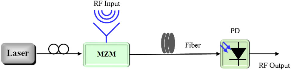
Figure 1 illustrates the fundamental concept of a typical externally modulated RoF link, which contains an optical modulator, a fiber link, and a photodetector (PD). Linear conversion between the lightwave and microwave determines the upper limit of the dynamic range of the RoF link, which influences the performance of the whole MWP system. However, the intrinsically nonlinear transfer function of the Mach–Zehnder modulator (MZM) may introduce both harmonic and IMD, which limits the linear conversion of the lightwave and microwave. Analog fiber-optic links with high SFDR can manage both weak input signals and signals with strong power and are especially attractive for both commercial and military applications [12–14].
Figure 1.Fundamental setup of externally modulated RoF link.
Besides, the capability to transfer the RF signal with stabilized phase to a remote location over the fiber link is also highly desired in many occasions, such as phased-array radar and connected-element interferometry applications. The advantages of an optical fiber link as a transmission medium make it the ideal solution for efficiently transporting radio signals from a central office to remotely located sites [15]. However, the fiber link suffers from environment perturbations, such as physical vibration and temperature fluctuation, which degrade the phase stability to be delivered. Therefore, knowing how to realize stable RF signal phase control is very important.
In this part, we discuss two methods for high-dynamic-range RoF links and highly stable RF delivery links, respectively.
1. High-Dynamic-Range RoF Links
To improve SFDR performance, numerous approaches have been demonstrated in recent years. The general design idea behind most of the aforementioned proposals is to introduce desired nonlinear distortions, which can be used to reduce the strength of the existing ones with the cost of increased system complexity. To overcome the challenge of linearity conversion, a linearization technique incorporating direct optical carrier band (OCB) processing has been investigated [16]. Rather than generating a certain distortion to cancel the existing one, we analyze the main optical spectrum contributors of the IMD3 and suppress them directly in the optical domain. By introducing a special phase shift to the OCB, the IMD3 is significantly suppressed. Note that the simplicity of the structure is also preserved.
There are three pairs of main contributors for the IMD3. When a phase shift of arcos () is imposed to the OCB, both the phase and amplitude conditions among the three main contributors of IMD3 are changed to the desired value, and the three different IMD3 contributors cancel each other. A proof-of-concept experiment based on the OCB processing is constructed, as shown in Fig. 2(a). The modulated signal is introduced to the following OCB processor for the phase adjustment. A fundamental-to-IMD3 ratio of more than 64 dB is obtained for the OCB processing approach due to the effective IMD3 suppression, while the fundamental-to-IMD3 ratio is about 30 dB for links without compensation, as shown in Figs. 2(b) and 2(c). The SFDR of the link is shown in Fig. 2(d), increasing from 99.6 to , as compared with conventional links without the OCB processing.
Figure 2.(a) Experimental arrangement for the IMD3 suppression in analog fiber-optic link employing OCB processing. Electrical spectra of the output fundamental signal and their IMD3s for (b) the conventional link without any processing in the optical domain and (c) the proposed link with OCB processing. (d) Two-tone measurement results for the compensated and uncompensated links. ESA, electrical spectrum analyzer.
So, we use a simple method to realize the linear conversion between the microwave and lightwave, by comprehensively investigating the main optical spectrum contributors of the IMD3 components in intensity-modulated directly detected analog fiber-optic links. The SFDR of the link is increased from to . Suppression of the IMD3 is performed by direct processing in the optical domain. Neither predistortion nor a complex modulator combination is required to cancel the existing distortions. The simplicity of the scheme is then preserved. The proposed technique can be greatly promoted for analog optical links whose simplicity and preferable SFDR specification are especially demanding.
Besides the above online-processing method for improving the SFDR, we propose an advanced digital signal processing (DSP) technique to correct the nonideal characteristics and the phase ambiguity effect in the coherent receiver of a phase-modulation and coherent-detection RoF link to further increase its dynamic range [17]. The experimental results show that a suppression of the IMD3 of more than 30.7 dB is achieved and the SFDR can be improved , which leads to a shot-noise-limited SFDR of . In addition, a simplified multiband digital predistortion (DPD) technique for subcarrier multiplexed RoF systems is proposed [18], which is performed on the baseband signal of each individual RF band before upconversion and RF combination to reduce the requirement of the hardware bandwidth. Experimentally, the adjacent channel powers of the signals on the two bands are suppressed by up to 15 dB, and their error vector magnitude (EVM) performances are significantly improved. Finally, the multidimensional DPD method is also demonstrated in both directly modulated and externally modulated multiband RoF systems [19].
In addition, there are other groups that make use of the highly linear RoF system. For example, researchers at the University of California, Los Angeles have proposed a digital algorithm that can achieve a 35 dB suppression of the IMD3 over multiple octaves of the signal bandwidth [20]. By regenerating undesired distortions and subtracting it from the distorted digitized signal, a SFDR of over 6 GHz is demonstrated. Besides, a single-drive dual-parallel MZM (SD-DPMZM)-based linearization approach is proposed [21]. By properly optimizing the working points of the SD-DPMZM, two kinds of origins of IMD3 can cancel each other; hence, the output IMD3 is suppressed dramatically. A SFDR of up to is experimentally demonstrated.
2. Highly Stable RF Delivery over Fiber Links
To realize the RF phase controlling, we propose and demonstrate a phase-compensation scheme that supports long-distance RF standard delivery over conventional fiber communication networks [22]. The active compensation loop consists of a large-tunable-range optical delay and a regular phase discriminator. The proposed scheme takes advantage of the large accumulated link dispersion, under which optical carriers with different wavelengths propagate at different velocities in the fiber, resulting in a “-dispersion” tunable delay.
The proposed stable RF delivery scheme is shown in Fig. 3(a). In the center station, the RF standard signal, centered at , is modulated on a wavelength tunable laser (WTL) through a MZM. The optical signal is transferred to the remote end, reflected by a Faraday rotation mirror (FRM), and then transferred back along the same fiber. In the center station, the round-trip signal is boosted by an erbium-doped fiber amplifier (EDFA), recovered by a fast PD and then bandpass filtered. The phase error is obtained by using a phase discriminator to compare the recovered signal with the original standard. The generated phase-error signal, which is actually twice the phase perturbation of the fiber link, is digitalized and used to alter the wavelength of the WTL. A classic proportional-integral-derivative (PID) algorithm is used during the above-mentioned feedback control. At the remote end, 20% of the optical power, out of an optical coupler (OC), is boosted, opto-electronically converted, and bandpass filtered as the final output.
Figure 3.(a) Experimental setup of the proposed phase error correction system. BPF: bandpass filter. (b) RMS jitter of the remote RF signal without (blue line) and with (red line) phase error correction. (c) SSB phase noise of the RF source and signal at the remote end.
Assume that the initial wavelength of the optical carrier is , the fiber delay fluctuation that results from the environment variation is , and the total link dispersion is . Tuning the WTL to results in the -dispersion delay according to . As a result, the phase fluctuations at the remote end and center station are and , respectively, under the assumption that the forward and backward propagations through the same fiber link experience the same time delay. As long as the PID phase tracking at the center station adjusts the wavelength of the WTL so that the round-trip phase fluctuation is zero, the RF phase in the remote end will also be stabilized.
Experimentally, we compare the phase delivery stability without and with the proposed fluctuation compensation. In the experiment, a 54 km single-mode fiber (SMF) is located at the laboratory. The output signal is observed by the sampling oscilloscope, which is trigged by the same 2.42 GHz reference at the center station. In the uncompensated delivery, the wavelength of the optical carrier is fixed at 1550 nm, while the other conditions remain the same as those in the compensated situation. The time jitter of the waveform is measured and shown in Fig. 3(b). During the whole seconds recording time, the uncompensated root mean square (RMS) time jitter is as large as 502.3 ps. When the wavelength tuning driven by the PID phase tracking is on, the RMS time jitter is compressed to be 0.854 ps. The phase drift is effectively suppressed with a ratio of 588. We also measured the single sideband (SSB) phase noise between 3 and 100 Hz with a spectrum analyzer. The results, which are plotted in Fig. 3(c), indicate that the compensation scheme has little effect on short-term stability. Then, using the whole dispersion link as a part of the tunable device, a range as large as tens of nanoseconds can be achieved. Fine and rapid delay tuning is experimentally demonstrated. Finally, broadband stable RF signal delivery with a large compensation range is achieved.
Furthermore, in cooperation with Beijing Aerospace Control Center, we have successfully used our broadband, multifrequency stabilized RF delivery link in the phase-based radiometric system in lunar radio measurement with Chang’E-3 satellite.
B. Fine Processing and Handling of Broadband Microwave Signals
Broadband processing capability is one of the main advantages of photonics. However, the processing fineness is the limited factor in the optical domain. In contrast, electronics have a fine or high-resolution processing capability, but the processing bandwidth is narrow, mainly limited by the analog-to-digital converter (ADC). Therefore, the crucial challenge is how to realize an effective combination between broadband photonics and fine electronics and then achieve a high system performance.
An optical frequency comb (OFC) bridges the gap between the broadband optical and the precise microwave in a single step, which is an essential way to solve this issue, as shown in Fig. 4. In this part, we will introduce two methods to realize a real-time, high-resolution monitoring of the entire RF spectrum and a scheme for multiband microwave frequency conversion.
Figure 4.Schematic of the system that combines broadband photonics and high-resolution electronics.
Besides, handling microwave signals in an integrated RF system for flexible information transition among multiple dimensions is very important, such as for microwave frequency conversion in a microwave repeater. In this section, we will introduce a comb-based multiband microwave frequency conversion method.
1. High-Resolution and Broadband Photonic RF Channelization System
Photonic channelization offers many advantages in dealing with ultrawide-bandwidth RF signals compared to pure electronic solutions [23–27]. First, it can take advantage of a large optical instantaneous bandwidth that current electronics technology cannot achieve. Second, channelization of broadband signals and translation into a common intermediate frequency (IF) can greatly reduce the requirements and cost of postprocessing electronics. We provide a means to channelize the broadband signal spectrum into frequency channels whose bandwidths are compatible with digital electronics [28]. Figure 5 shows the schematic of the channelization scheme, where the RF signals can be processed in parallel, which significantly simplifies the RF receiver’s hardware.
Figure 5.Configuration of the coherent OFC-based channelization scheme. PBS, polarization beam splitter; PBC, polarization beam coupler.
The use of two coherent combs avoids precise optical alignment, and the numerical filter in the digital signal processor enables an ideal rectangular frequency response in each channel without any ultranarrow optical filters. Besides, due to the use of polarization in-phase/quadrature (I/Q) demodulation, ambiguous frequency estimation in direct detection can be avoided while the amplitude and phase mismatch in traditional I/Q demodulation can be mitigated.
The proposed channelization scheme is shown in Fig. 5. The input broadband RF signal is upconverted and multicast by optical lines in the first OFC; these copies are then physically separated by a regular optical de-mux, each of which is mixed with the other channelized OFC. Because of the difference in the free spectral range (FSR) of the two combs, different spectrum slices of the RF signal are extracted and downconverted to baseband or IF by the followed polarization I/Q demodulators. Finally, I and Q tributaries are synthesized in the DSP unit.
We experimentally tested the scheme by inputting single and dual RF tones. The two OFCs with 40 GHz FSR are coherent, and the channelizer equally divides the 3.75–7.25 GHz band seamlessly into seven channels. First, we tested the scheme by inputting a single RF tone placed at 4.111, 5.55, and 6.63 GHz. The downconverted IF tone is expected to be 111, 50, and 130 MHz in theory, which appears in the first, fourth, and sixth channel, respectively. In the experiment, the IF tone is digitalized with the sampling rate of and sampling time of 100 μs. Then, the spectrum is calculated offline and shown in Fig. 6.
Figure 6.Output of the first, fourth, and sixth channels when RF signals of 4.111, 5.55, and 6.63 GHz are inputted, respectively.
We can observe that each RF tone is correctly downconverted and channelized exactly as the theory predicts. The IF frequency errors () originate from the frequency errors of our microwave sources. Note that spurious tones (located at the harmonic components of the detected IF) come from: (1) slight phase and amplitude mismatch between I and Q tributaries and (2) nonlinearity of the real-time sampling oscilloscope.
The crosstalk and frequency response of the channelization scheme are measured. In theory, due to the ideal rectangle filtering response of the numerical filter, the out-of-channel cross talk can be removed. In our experiment, the input RF tone is placed at 6.055 GHz (the corresponding IF locates in the fifth channel). Then, the outputs of the fifth channel and the next-nearest neighbor channels (fourth and sixth channels) are measured and shown in Fig. 7(a). No related IF tones are observed in the fourth and sixth channels, which is in good agreement with the theoretical analysis. But in both channels, there is a small dc component, which comes from the imbalance of the balanced photodetectors (BPDs).
Figure 7.(a) Output of the fourth, fifth, and sixth channels when 6.055 GHz signal is inputted. (b) Normalized channel response of the third channel with center frequency of 5 GHz and channel width of 500 MHz.
To measure the channel frequency response, a sweeping RF tone is applied to the MZM. The third channel is measured from 4.75 to 5.25 GHz with a 25 MHz step. The normalized amplitude response is shown in Fig. 7(b). One can observe that the channel response is a rectangle-type function: (1) inside the channel, the proposed channelization scheme has fine channel response uniformity (1.44 dB) and (2) out of the channel, no IF is outputted, which agrees with analysis in theory.
Therefore, by using two coherent OFCs with a FSR of about 40 GHz, we demonstrate the channelization scheme with seven channels, 500 MHz channel spacing, and frequency coverage from 3.75 to 7.25 GHz. The input RF tones are accurately downconverted to an IF with a maximum frequency error of 125 kHz.
2. Compressive Sampling System
Over a broad frequency range, it is highly desired to provide the RF spectrum information of the intercepted signal with multifrequency resolving, high accuracy, and real-time operation. Several photonics-based multifrequency resolving approaches have been demonstrated [25,26,29]. Note that in a radar system, especially in military circumstances, the RF signal under detection is generally spectrally sparse; it contains multiple RF components covering a broadband but possesses little energy, and compressive sampling theory is a promising methodology for reconstructing sparse signals with very few measurements. We experimentally demonstrated a simple optical multifrequency sensing system to recognize the frequencies compressively without large computational load [30]. The frequencies of multitone RF signals ranging randomly from 0 to 1 GHz are recognized precisely with negligible errors.
The proposed experimental setup of the multifrequency RF sensing system is shown in Fig. 8(a). The continuous-wave (CW) light is modulated by an -bit pseudo random binary sequence (PRBS) through a MZM that is biased at the quadrature for further encoding. The RF signal, , which contains multiple RF tones whose frequencies are unknown, is modulated onto the PRBS by a MZM, which is properly biased in order to obtain complementary optical power at its two outputs. If the time delays from the outputs of the MZM to the inputs of the BPD are equal, under small signal approximation, the output, , of the BPD is in direct proportion to the encoded signal, . The employment of the MZM and BPD not only provides a higher SNR but also eliminates some unwanted terms in the product. After passing a low-pass filter (LPF), only the baseband signal with analog bandwidth is digitalized by an ADC that works at a relatively low rate. Finally, the data is sent into the DSP unit which is an offline MATLAB program in our experiment.
Figure 8.(a) System configuration of the proposed scheme. (b) Spectrum of a single tone. (c) Spectrum of PRBS. * denotes convolution. (d) Spectrum of the encoded signal. The dashed green line indicates the frequency response of the LPF. (e) Enlargement of the LPF’s passband. The dashed red line denotes the case of inputting another RF tone. PPG, pulse pattern generator; AWG, arbitrary waveform generator.
An intuitive explanation that involves inputting one RF tone is illustrated in Figs. 8(b)–8(e). Assuming there is only one tone in , such as , is the spectrum of PRBS . So stands for the spectrum of the encoded signal . As shown in Fig. 8(b), within the passband of the LPF, each tone has a distinct signature that overlaps with others. However, since the two signatures are nearly orthogonal when their phases are taken into account and there are few tones present, it is possible to identify the tones from the incomplete information (only baseband information). In order to use the limited information fully and efficiently, we propose that by calculating the cross-correlation function between the PRBS and the encoded signal after the LPF, the frequency of the tone can be recovered without a large amount of computation. The cross-correlation function can be expressed as where is the conjugate function of . denotes within , which is approximately a constant if the chip rate of the PRBS is high enough.
Since the cross-correlation between and is only a shifted version of the self-correlation of , let us analyze the self-correlation of first. The pseudo noise feature of PRBS guarantees that has unit magnitude and uniformly distributed phase. So the complex amplitude of can be viewed as noise. Consequently, the self-correlation function of this noise-like function results in a single peak at and at , where has very low amplitude. This will be proved in our experiment later. When the cross correlation between encoded multitone signal and PRBS is calculated, the self-correlation function will be first shifted to the frequencies of input tones and will then be summed up to obtain a cross-correlation function. So by recognizing the frequencies of peaks in the cross-correlation function, we can obtain the frequencies of input signal easily. Note that will be summed up in the cross correlation too, so the noise floor of the cross correlation will increase as more frequencies are inputted into our system simultaneously. The will also increase by using a narrower bandwidth LPF since less information will be sent into the DSP unit for reconstruction.
In our experiment, first, to obtain , only the PRBS is modulated onto the CW light without inputting RF tones. The self-correlation function of is shown in Fig. 9(a). It shows that is 65 dB lower than the peak at , which verifies the good self-correlation characteristic of . Second, the PRBS and the RF signal with 20 tones are sent into the system simultaneously. The RF signal contains frequencies that are at the two edges of the (0.0002 and 0.9998 GHz) and are extremely close and equally spaced with (0.24996, 0.25, 0.25004 GHz). All the 20 frequencies are recovered precisely as shown in Fig. 9(b). Finally, a RF signal with up to 40 tones is sent into our system. All the frequencies are distinguished accurately with the SNR above 10 dB, as shown in Fig. 9(c).
Figure 9.Experimental results. (a) Self-correlation function of . (b) Input and recovered spectrum of a RF signal with 20 tones. (c) Input and recovered spectrum of a RF signal with 40 tones ranging from 0.1 to 1 GHz.
Therefore, we propose a compressed multifrequency RF sensing method with photonic assistance. The frequencies of a 40-tone RF signal ranging randomly from 0 to 1 GHz are recognized precisely.
3. Multiband Microwave Frequency Conversion System
An integrated RF system that is capable of sharing data or functionality with other systems requires flexible information transition among multiple dimensions, such as frequency or space domain. However, the demands on great capacity and large instantaneous bandwidth have driven today’s RF system to operate at higher frequencies and more bands. Conventional purely electrical RF techniques are coming up short when dealing with multiband, high-frequency signals since electrical devices have limited response bandwidth and strong electromagnetic interference. Recently, MWPs, with its unique characteristics of parallel signal processing over an extremely wide bandwidth, is emerging as a powerful tool for constructing complicated RF systems, such as the European Space Agency’s SAT’N LIGHT project [31] and the Atacama Large Millimeter Array [31]. In our recent research [32], by introducing MWP techniques, we proposed a single structure that integrated several main functions: multiband local oscillator (LO) generation and distribution, multiband RF frequency conversion, and cross connection. Thanks to MWP techniques, we are able to simultaneously handle multiple RF frequencies even beyond the Ka band. Moreover, the systems can be more cost effective, power efficient, and space saving by sharing a single structure.
Specifically, the implementation is divided into three steps: multiband LO generation, electro-optical mixing, and channelized heterodyne. As illustrated in Figs. 10(a) and 10(b), different microwave LOs can be obtained by heterodyning dual coherent OFCs with slightly different mode spacing, say and , and an offset between their center comb lines. The values of , and are carefully assigned so that every comb-line pair that is composed of the comb lines from the two OFCs with the same index falls into each passband of a periodic optical filter, such as a wavelength division multiplexer (WDM). By heterodyning each pair of these comb lines in each passband, multiple microwave LOs can be achieved with a series of frequencies: where the index () denotes the order of the comb line relative to the center mode and is the maximum order of the available comb line. It is noted that to avoid spectral aliasing, the values of , , and should satisfy the following relations: where denotes the passband width of the WDM filter.
Figure 10.(a) Schematic diagram of multiple LO generation, electro-optical mixing, and channelized heterodyne detection. (b) Illustration of multiband LO generation. (c) Illustration of signal multicasting and the instantaneous bandwidth.
It is worth noting that the structure can be configured to implement frequency multicasting by simply inserting an electro-optical (E/O) mixing module into one branch of the structure, as shown in the dashed line box of Fig. 10(a). An input signal within a supported bandwidth is replicated besides each comb line of one OFC under a carrier-suppressed SSB modulation manner, as shown in Fig. 9(c). The signal OFC then combines with the other OFC (Local OFC) and goes through channelized heterodyne detection. Then multiple converted signals within different bands are obtained:
Theoretically, for the mixing process shown in the inset of Fig. 10(c), the Nyquist criterion implies that signals appearing in the second and third Nyquist zones will lead to aliasing problem after frequency conversion [33]. Hence, only one Nyquist zone can be used for operation. If we choose the LO comb line’s left side space (within the second Nyquisit zone) as the operation bandwidth, considering that the LO comb lines locate at different positions in the filter passbands, the supported instantaneous bandwidth in the th channel can be given by
In the experiment, as shown in Fig. 11(a), dual coherent OFCs with 18 GHz center frequency shift and 38 and 30 GHz mode spacing are generated. The flatness of both OFCs is less than 0.9 dB and unwanted mode-suppression ratios are greater than 14.7 dB. After channelization and heterodyne detection, different bands of frequency components at 2, 10, 18, and 26 GHz, which can be taken as multiband LOs, are obtained. As Figs. 11(c)–11(f) show, the SNRs of the multiband LOs are between 31 and 52 dB in 2 GHz bandwidth under a resolution bandwidth (RBW) of 20 kHz.
Figure 11.(a) Dual coherent OFCs with 18 GHz center frequency shift and 38 and 30 GHz mode spacing. (b) Channelized dual OFCs, with one carrying the signal. (c)–(f) Generated multiple LOs within different bands. (g)–(i) Multicast signals within different bands. (j) EVM test results of the multicast signals.
When the structure is configured to implement signal multicasting, an input C band frequency of 6.1 GHz is successfully converted to 4.1, 3.9, 11.9 GHz in separate channels. The first three results are shown in Fig. 11(g)–11(i) with SNR between 30 and 46.7 dB under 20 kHz RBW measurement condition. The evaluation of the system performance shows that a 9.3% EVM degradation compared with the back-to-back case is observed at 0 dBm input power. Furthermore, all the results are far below the maximum EVM limit of 31.6% for quadrature phase-shift keying (QPSK) signal in a very wide power range.
C. Efficient Utilization and Dynamic Management of the Resources in the DASs
The point-to-point, high dynamic, and phase-stabilized RoF links are able to reconstruct a centrally managed point-to-multipoint DAS, which can realize broadband, ubiquitous, and convergent wireless access or high-resolution aerospace measurement and controlling and astronomy monitoring. For broadband wireless access, DAS using RoF links has been demonstrated as a commonly used infrastructure solution to provide broadband wireless coverage within a geographic area with reduced total power and improved reliability [34,35]. In some DAS applications, a single set of base-station facilities in the center unit is connected to multiple antenna units (RAUs) to extend the indoor coverage of one base station and to share the bandwidth resource. This kind of DAS is often called a simulcast DAS, where a single base station simultaneously broadcasts wireless signals to multiple RAUs in the downlink. In the uplink, the user stations covered in different RAUs contend for the shared transmission medium and base-station facilities. A great number of wireless service providers or carriers around the world have deployed simulcast DASs (not limited to RoF DASs) in buildings and public venues for improving the quality of the indoor third-generation and long-term evolution (LTE) coverage. With the shared cable network infrastructure, wireless local-area network (WLAN) signals are also preferred to be distributed in the same buildings and public venues as an important complement to LTE.
The IEEE 802.11 media access control (MAC) protocols were originally designed and standardized for WLANs. In a simulcast WLAN RoF DAS, the coverage of one access point (AP) is enlarged into a greater scale and many more user stations communicate with the AP through multiple different fiber-connected antennas. Therefore, it is in strong demand to investigate the performance of the existing IEEE 802.11 MAC protocols in simulcast WLAN RoF DASs. The IEEE 802.11 standards suggest two mechanisms or so-called coordination functions in the MAC layer [36]. The first one is the widely used distributed coordination function (DCF) [37,38], which can work in two modes: the basic access mode and the request/clear to send (RTS/CTS) exchange mode. The other one is the point coordination function (PCF). In this section, we analyze both the DCF and PCF performance in a simulcast WLAN RoF DAS in terms of different fiber links [39]. Two optional architectures for simulcast WLAN RoF DASs are shown in Fig. 12. The simulcast function can be achieved both in the RF domain and the optical domain. In both architectures, a number of RAUs distributed in separate locations are connected with different-length fiber links to a single WLAN AP located in the central unit.
Figure 12.Typical simulcast WLAN RoF DAS architecture.
For describing the DCF performance in a simulcast RoF DAS accurately, we present an analytical model based on the two-dimensional Markov chain model, considering the fiber length difference effects. Figure 13 describes the throughput performance in both modes of DCF as the fiber-length difference between RAU-A and RAU-B increases. We can find that the basic access mode is shown to have a more serious throughput discrepancy between RAUs. From Fig. 12, we can see that the maximum throughput difference between RAU-A and RAU-B is 87% in basic access mode and 56.9% in RTS/CTS exchange mode.
Figure 13.Comparison of fiber effect via different fiber delays between RAU-A and RAU-B. Solid lines represent basic access mode and dashed lines represent RTS/CTS exchange mode.
The most different characteristic of the PCF is that it achieves coordination through a centralized algorithm, where the AP runs the algorithm, while the DCF has a distributed algorithm run by all the stations. For PCF, all the stations in the polling list are polled by a point coordinator normally situated in the AP. The PCF uses a centralized resource scheduler, where a single AP controls the associated stations’ access to the channel by sending the polling messages. With its strong characteristics of a centralized allocation scheduler, we want to use it to improve the throughput performance in a simulcast RoF DAS, where the stations covered in different located RAUs can barely sense each other properly. A strong demand for a centralized allocation arises because of the needs of the blind stations. As observed from Fig. 14(a), the proposed improved PCF outperforms DCF in both basic access and RTS/CTS modes, which proves the prediction that the adaptive PCF can avoid the inter-RAU hidden-node (HN) problems through its centralized polling mechanism, especially over shorter-length fiber links.
Figure 14.(a) Normalized throughputs for the basic-access DCF mode, DCF in RTS/CTS mode, and adaptive PCF as a function of the number of RAUs assuming identical fiber length. (b) Throughput performance of each RAU as the function the length of one of the fiber links assuming different fiber lengths in a two-RAU scenario.
Figure 14(b) depicts the throughput performance of each RAU as the function of the fiber length between the AP and RAU-B. Although the overall throughput slightly drops for each RAU as the fiber length of RAU-B increases, a much smaller performance deviation between the two RAUs can be observed in the adaptive PCF mode, which indicates that the adaptive PCF provides more fairness to all the stations covered by every RAU in the presence of fiber-length differences.
So the performance of several key WLAN MAC mechanisms has been investigated in simulcast RoF DASs, including the DCF in both the basic access and RTS/CTS exchange modes, and the PCF. It is shown that the adaptive PCF is a promising mechanism for simulcast RoF DASs in terms of the overall throughput and fairness among RAUs.
3. APPLICATION AND FUTURE WORK
A. Multiband Satellite Repeater
According to the information-mapping principles between microwaves and photonics, we propose a satellite repeater architecture that consists of multiple paths to support repeating signals among the C, Ku, K, and Ka bands [32], as shown in Fig. 15. Note that all the paths share a common LO generation module and an optical switch matrix that dramatically saves LOs and space on the satellite. The whole system can be divided into three sections: the multiband LO generation section, the band-to-band conversion section, and the optical cross-connect section.
Figure 15.Conceptual architecture of multiband satellite repeater based on OFCs. LNA: low noise amplifier.
In particular, these three sections can be compatible with each other since all their functions are implemented in the optical domain. Consequently, this concept of a MWP repeater is very suitable for transparent and broadband telecom missions. Besides, such a MWP system with a parallel structure offers high scalability so that it can be upgraded to large scale with the number of channels. In the future, once integrated in a single chip, this concept will bring the current all-microwave repeaters to a new era with unprecedented performance improvement.
B. Intelligent and Dynamic Controlled Next-Generation Wireless Information System
The conceptual architecture of the next-generation intelligent wireless information system is illustrated in Fig. 16. This system consists of three main parts: the software-defined radio (SDR) office, the MWP processing system, and the remote units. The SDR provides a flexible, upgradeable radio platform for military and civilian wireless communications, which can flexibly change the radio waveform by simply loading the appropriate software without modifying the whole SDR platform (i.e., keeping the hardware and operating environment where the waveform application is running). Besides, the SDR office includes an SDR platform and refined electronic RF processing system, which is used for centralized resource management and dynamic spectrum allocation. Moreover, the MWP system uses the strength of photonic techniques to generate, distribute, process, receive, and analyze RF signals. Because of the combination of the advantages of both electronic and photonic, this intelligent, ubiquitous, and programmable wireless information system can provide larger bandwidth coverage, higher data rates, and higher mobility, which will be suitable for many applications and situations.
Figure 16.Conceptual architecture of a next-generation intelligent wireless information system.
Microwave photonics (MWPs) combines the advantages of microwaves and photonics, which is an interdisciplinary area that studies the interaction between microwaves and lightwaves. However, there are still several challenges in strengthening the performance of the technology to support systems and applications with a more complex structure, multiple functionality, larger bandwidth, and enhanced processing capability. In this paper, we addressed some of the challenges in MWP and presented the progress of our work in three main area: (1) high-linearity conversion and control between the lightwave and microwave; (2) precise processing and handling of broadband microwave signals; and (3) efficient utilization and dynamic management of the resources in the DASs. Finally, some applications and future directions of research based on those systems are discussed, especially, an intelligent wireless information system using a SDR for centralized management and MWP systems for photonic RF processing is proposed.
[8] M. Sotom, B. Bénazet, A. Le Kernec, M. Maignan. Microwave photonic technologies for flexible satellite telecom payloads. Proceedings of the 35th European Conference on Optical Communication, 1-4(2009).
[17] Y. Pei, J. Yao, K. Xu, J. Li, Y. Dai, J. Lin. Advanced DSP Technique for dynamic range improvement of a phase-modulation and coherent-detection microwave photonics link. International Topical Meeting on Microwave Photonics, 72-75(2013).
[26] D. B. Hunter, L. G. Edvell, M. A. Englund. Wideband microwave photonic channelized receiver. International Topical Meeting on Microwave Photonics (MWP), 249-252(2005).
[34] M. J. Crisp, S. Li, A. Wonfor, R. V. Penty, I. H. White. Demonstration of a radio over fibre distributed antenna network for combined In-building WLAN and 3G coverage. Optical Fiber Communication and the National Fiber Optic Engineers Conference, 249-252(2007).
[37] A. Zhou, M. Liu, X. Jiao. Convergence analysis and its application in the fixed point formulation of medium access in wireless network. China Commun., 8, 43-49(2011).
[38] S. Wang, A. Hafid, H. Zhao, S. Huang, C. Xiong, J. Wei. Towards wide-open, adaptable DCF implementation for dynamic networks. China Commun., 8, 77-89(2012).