R. Gonzalez-Arrabala), A. Rivera, and J. M. Perlado
Abstract
The high-power laser energy research (HiPER) project was a European project for demonstrating the feasibility of inertial fusion energy based on using direct-drive targets in a shock ignition scheme using a drywall evacuated chamber. HiPER was intended to drive the transition from a scientific proof of principle to a demonstration power plant in Europe. The project was divided into three realistic scenarios (Experimental, Prototype, and Demo) to help identify open problems and select appropriate technologies to solve them. One of the problems identified was the lack of appropriate plasma-facing materials (PFMs) for the reaction chamber. Therefore, a major challenge was to develop radiation-resistant materials able to withstand the large thermal loads and radiation in these reactors. In this paper, we describe the main threats that coarse-grained W would face in the diverse HiPER scenarios. Based on purely thermomechanical considerations, the W lifetimes for the HiPER Prototype and Demo scenarios are limited by fatigue to 14 000 h and 28 h, respectively. The combined effects of thermal load and atomistic damage significantly reduce these lifetimes to just ~1000 shots for the Experimental scenario and a few minutes and seconds for the Prototype and Demo scenarios, respectively. Thus, coarse-grained W is not an appropriate PFM for the Prototype or Demo scenarios. Therefore, alternatives to this material need to be identified. Here, we review some of the different approaches that are being investigated, highlight the work done to characterize these new materials, and suggest further experiments.
I. INTRODUCTION
Nuclear fusion is a promising option for providing clean energy, and it may be able to fulfill the increasing energy demands worldwide. It would help to meet the decarbonization requirements recognized by EURATOM within the Horizon Europe research program, which is to run from 2021 to 2027. The main advantages of nuclear fusion compared to other clean energy sources are its high-power density and reliable power supply. However, to make fusion a reality, some weak points must be overcome. Some of these are related to plasma physics and reactor technology, whereas others are related to the development of materials able to withstand the harsh reactor environment (mainly high thermal load and high radiation flux). Indeed, the lack of suitable materials is a major concern.
There are two main approaches to fusion energy: magnetic confinement fusion (MCF) and inertial confinement fusion (ICF). The current choice for an ICF driver due to its superior capabilities is a laser; thus, ICF is also called laser fusion. There are important technological differences in ICF between direct-drive targets (in which laser beams directly illuminate the target) and indirect-drive targets (in which the laser energy is converted to x-rays, which illuminate the target). The most advanced project to demonstrate the viability of MCF is the International Thermonuclear Experimental Reactor (ITER), now under construction in France with support from organizations in Europe, Asia, and the USA.1–3 For ICF, the most relevant projects are the National Ignition Facility (NIF) in the USA,4,5 the Laser Megajoule (LMJ) and PETawatt Aquitaine Laser (PETAL) in France,6 OMEGA in the USA,7 the Fast Ignition Realization Experiment (FIREX) in Japan,8 and also projects in Russia and China.
To prepare for the next step in constructing a power plant, the MCF community is proposing demonstration projects in Europe,9,10 Japan,11 Russia,12 Korea,13 and China.14 Similarly, the ICF community has proposed two projects: HiPER (high-power laser energy research) in Europe and LIFE (laser inertial fusion energy) in the USA, which use direct-drive15–18 and indirect-drive19–23 targets, respectively. Direct-drive targets have a simpler design and may have a higher gain than indirect ones because the efficiency is not reduced by the creation of x-rays. In addition, advanced ignition schemes,24 such as shock ignition (as in HiPER) are much easier to implement with direct-drive targets.
The European HiPER project aimed to study the possibility of laser fusion with direct-drive targets, shock ignition, and a drywall evacuated chamber. A full demonstration plant was considered.25 The project was divided into three scenarios corresponding to different phases in the development of nuclear fusion technology: experimental facilities (Experimental scenario), a power plant operating in relaxed mode far from full power (Prototype scenario), and a full-scale demonstration power plant (Demo scenario). Other projects, such as HAPL26 and ARIES27 in the USA, and KOYO-F,28 LIFT,29 and FALCON-D30 in Japan, had the same goals, which were based on central ignition (USA) or fast ignition (Japan).31,32
In shock ignition,33,34 the D-T target is first compressed to high density by shooting a long laser pulse directly on to its surface. When maximum compression is achieved, a convergent spherical shock wave is launched into the compressed fuel using a high-intensity spike in the laser pulse. According to simulations, this promotes pressure amplification and ignition. Shock ignition significantly reduces the laser energy required for ignition in comparison to fast ignition.34 Apart from the differences in the way in which ignition is attained, in all direct-drive approaches, after ignition, x-rays, high-energy neutrons (11 MeV–12 MeV),35 and ions (keV–MeV) are produced.
Plasma-facing materials (PFMs) are directly exposed to the target explosion. They protect the structural material from the irradiation. Thus, a PFM must have excellent structural stability, since severe cracking or mass loss would reduce its protective role. It also has to have: (i) high thermal shock resistance, (ii) high thermal conductivity, (iii) high melting point, (iv) low physical and chemical sputtering, and (v) good compatibility with the coolant. Moreover, for safety reasons, low tritium retention is also a must.
Due to its properties, W is a candidate PFM.36 However, previous work indicates that W has important drawbacks, such as its high ductile-to-brittle transition temperature (423 K–673 K),37 low yield strength,38 oxidation at elevated temperatures into WO3,39 and recrystallization well below its melting temperature.40,41 Moreover, it has a very detrimental ability to retain light species easily, mainly hydrogen42–45 and helium,43,46 which leads, among other fatal effects, to surface blistering, cracking, and exfoliation.
The performance of W under H, He, and to a lesser extend under mixed (H + He) irradiation has been studied under diverse irradiation conditions.42–48 Because the effects of radiation depend on the irradiation conditions (ion energy, flux, fluence, and temperature) and on sample characteristics (defects and impurities), data sets must be compared carefully, especially when trying to extrapolate results (e.g., from low-flux low-energy to high-flux high-energy experiments). The pulsed nature of the most relevant irradiation events in both ICF and MCF requires special consideration, because pulsed and continuous irradiation cause different types of damage to materials.49,50 Note that under pulsed irradiation, the damage also depends on the pulse conditions (pulse duration, repetition rate, and whether the samples suffer thermal loads concurrent to the pulses).50
Thus, when studying the effects of ion irradiation in HiPER, one should recreate, as far as possible, the particular irradiation conditions. These include hundreds to thousands of nanosecond pulses comprising a high flux (1022 m−2 s−1–1025 m−2 s−1) of high-energy light ions (ranging from keV for debris to MeV for fast burn products) and simultaneous pulsed thermal loads (of up to 105 MW m−2). Testing materials under these irradiation conditions requires dedicated facilities. To the best of our knowledge, there is no facility that can test materials under realistic conditions, which hampers the characterization of irradiation effects for the materials proposed for HiPER as well as for other inertial fusion reactors operated in the direct-drive configuration.
So far, the most relevant experiments studying the effects of irradiation on PFMs in reactors like HiPER have been performed in the repetitive high-energy pulsed power facility (RHEPP-1)51 at Sandia National Laboratories and in high-energy plasma focus (PF) devices all around the world.52–56 In RHEPP, samples were exposed to up to more than 1000 pulses of high-energy ions (500 keV–900 keV) at energy fluences up to 8 J/cm2, for a pulse duration of ∼100 ns, and repetition rates close to 0.1 Hz. High-energy PF devices produce pulses with a duration of hundreds of nanoseconds with a high flux (1022 m−2 s−1–1025 m−2 s−1) of high-energy ions (ranging from keV to MeV).57 However, RHEPP-1 was dismantled and using PF devices to study the effects of irradiation on materials is not trivial because it is necessary to achieve precise control and reproducibility of the irradiation conditions, which is difficult for these devices. Currently, efforts are focused on accurately characterizing the radiation environment in PF devices. Indeed, the International Atomic Energy Agency is promoting coordinated research projects to do this and58 is bringing together specialists on PF devices and materials scientists.59
Other facilities for testing PFMs for ICF reactors are those used by the MCF community for testing divertor materials.60 These are mainly linear plasma facilities, such as the Garching large divertor sample test facility (GLADIS)61 in Germany, or the neutral beam injection facility at the National Institute of Advanced Industrial Science and Technology in Japan.62 These two facilities can generate pulses with a high flux (∼1021 m−2 s−1) of high-energy (keV) ions with a duration of seconds or microseconds, respectively. However, note that these facilities can estimate only the effect of pulsed irradiation by debris (keV) but not by fast burn products (MeV). Moreover, the differences in the duration of pulses generated in these facilities and those reaching a PFM in ICF should be considered. Nevertheless, the result of the experiments performed in these facilities, even when not fully reproducing the radiation environments in ICF, are very interesting, since at least they can be used to validate simulation codes, which are valuable for studying and developing materials. In this sense, collaborative work by the MCF and ICF communities would enhance progress, save money, and avoid duplication of results
In this paper, we review the harsh conditions (large thermal load and damage from high-energy ions) that W would face in the three HiPER scenarios: Experimental, Prototype, and Demo. Next, we study the performance of W under such harsh conditions and discuss the limitations of coarse-grained W (from now on W) as a PFM. Finally, we review new approaches that are being considered to develop more radiation-resistant materials, highlight the work done so far, and suggest some complementary studies that will be needed for the systematic characterization and definition of the operational limits of PFMs.
II. CHAMBER DESIGN AND IRRADIATION CONDITIONS
In HiPER, three different scenarios were considered: Experimental, Prototype, and Demo. The Experimental facility aimed to demonstrate an advanced ignition scheme and repetitive laser operation; therefore, irradiation was limited to bunches of a few shots with energies of ∼20 MJ. The Prototype power plant planned to study target injection, tracking, repetition mode, tritium production, heat extraction, and the effects of irradiation on materials. It was to operate under relaxed conditions (1 Hz and 50 MJ). Finally, the full-scale demonstration (Demo) power plant aimed to prove the feasibility of the technology under the operating conditions of a power plant (10 Hz and ∼150 MJ). The main operating conditions for the three diverse HiPER scenarios are shown in Table I.
| Experimental | Prototype | Demo |
|---|
| Frequency | Few shots per bunch | 1 Hz | 10 Hz |
| Shot energy (MJ) | 20 | 50 | 154 |
| Inner chamber radius (m) | 5 | 6.5 | 6.5 |
| Blanket | No | Yes | Yes |
| Total energy fluence of ions (J m−2) | 1.7 × 10⁴ | 2.5 × 10⁴ | 7.7 × 10⁴ |
| Heat flux factor, FHF (MW m−2 s0.5) | 9.7 | 14.4 | 44.4 |
| Maximum pulse temperature (K) | 875 | 1410 | 3400 |
| Maximum steady-state temperature (K) | … | 610 | 934 |
| Plastic region (×10−6 m) | 5 | 10 | 100 |
| Plastic strain range reached during the cycle load (Δεp) | 4.5 × 10⁻³ | ∼10−2 | ∼6 × 10⁻² |
| Allowed number of shots (based on purely thermomechanical considerations) | 270 × 109 | 5 × 10⁷ | 1 × 10⁶ |
| Lifetime based on thermomechanical considerations (hours) | Not applicable | 14 × 103 (580 days) | 28 |
| Lifetime based on synergistic effects (thermal loads and He irradiation) | ∼1 × 10³ shots | Minutes | Seconds |
Table 1. HiPER operating conditions for the three HiPER scenarios (Experimental, Prototype, and Demo) together with the main operating parameters and the predicted lifetimes based on purely thermomechanical considerations and on synergistic effects (combined effect of pulsed thermal load up to 105 MW m−2 and high-flux high-energy He irradiation).
In all scenarios, the reaction chamber has to be designed to fulfill diverse requirements, mainly related to proper target injection, laser beam transport, survivability, safety, maintenance, and clearance. One of the key issues for the chamber is identifying the optimum materials and chamber dimensions, which must be set to avoid or to minimize, as much as possible, damage to the chamber, to ensure the proper operation of the facility during its intended lifetime.
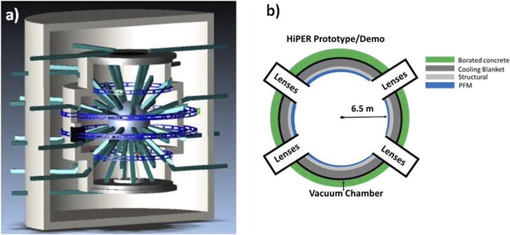
A definitive scheme for the HiPER reaction chamber was not defined. Nevertheless, some advanced concepts for it have been described.16,63 In all scenarios, the chamber was designed to be spherical, with 48 openings for the laser beamlines, allowing symmetrical target illumination (Fig. 1). As shown in Fig. 1(b), the chamber had concentric layers: (i) PFM (expected to be made of W),64 (ii) substrate, to give mechanical support to the PFM, and (iii) cooling blanket (for the Prototype and Demo scenarios).63,65

Figure 1.(a) Layout of the HiPER reactor. Reprinted with permission from J. M. Perlado et al., Proc. SPIE 8080, 80801Z (2011).18 Copyright 2011 SPIE Digital Library. (b) Schematic view of the chamber designed for the HiPER Prototype and Demo scenarios.
The irradiation spectra used as input data to calculate the radiation spectra in HiPER were taken from the ARIES project for a 154-MJ direct-drive target (Demo scenario),66 which was rescaled to 20 MJ and 50 MJ for the HiPER Experimental and Prototype scenarios, respectively.67 As reported in Refs. 68 and 69, the energy generated in the target ignition is carried by neutrons, energetic burn products (H, D, T, and He), and debris (D and T ions from unburnt plasma and low-energy He). Neutrons carry ∼71% of the energy released by the explosion and ions nearly 27%, while the remaining energy is carried by x-rays (1%–2%). The ion and x-ray spectra are reported in Refs. 69–71. The neutron spectrum is reported in Ref. 72.
Based on the chamber depicted in Fig. 1 and considering that the chamber radii in the Experimental scenario are 5 m and 6.5 m in the Prototype and Demo scenarios, the time of flight to reach the PFM in HiPER is shorter than a microsecond for fast burn products (D, T, and He) and around tens of microseconds for debris ions (slow D, T, and He). The time of flight of x-rays is negligible; thus, the x-ray pulse has a duration similar to the target illumination, around tens of nanoseconds. Therefore, in HiPER, the entire process of energy deposition in the PFM would last less than 10 µs. More precise data are published in Ref. 69.
Spatial energy profile for the different species in HiPER as calculated with the SRIM code,73 for ions, and the appropriate absorption coefficients for x-rays74 indicate that x-rays deposit most of their energy at depths <1 µm, deuterium and tritium debris ions at depths ≤2 µm, and most of the helium burn product ions at depths ≤4 µm. Note that most of the energy carried by x-rays and ions is deposited in the first few micrometers of the PFM. Around 90% is deposited at depths ≤5 µm. The most energetic ions (>2.5 MeV) deposit the remaining 10% at depths ≤100 µm. Figure 2 is a schematic overview of the most significant species produced from the explosion, showing their time of flight and the depth at which they deposit most of their energy. A more detailed description of the spatial and temporal radiation deposition can be found in Ref. 69.
Figure 2.Schematic overview of the most significant species produced in the explosion, together with their time of flight (TOF) and the depth at which they deposit most of their energy.
III. THREATS FOR W OPERATING UNDER HiPER CONDITIONS
A. Pulsed thermal loads
Due to the long penetration range of neutrons, they do not deposit their energy in the PFM, but deeper into the chamber wall. Therefore, only the energy carried by ions and x-rays is deposited in the PFM. Moreover, for direct-drive targets, as in HiPER, ions are the main contributors to the thermal load.
In the case of ion irradiation in which ions arrive at different times, a first assessment of the thermomechanical behavior of W can be made using the heat flux factor (FHF), which was introduced to normalize the thermomechanical effects of irradiation with pulses of different durations. It is defined as the product of the power surface density (Pabs) and the square root of the pulse duration (Dt): .
Figure 3 shows FHF values for the three HiPER scenarios together with values reported by Linke et al.75 and Renk et al.76 for surface deteriorations: roughening (FHF ≈ 20 MW m−2 s0.5), cracking (FHF ≈ 20 MW m−2 s0.5–50 MW m−2 s0.5), melting (FHF ≈ 70 MW m−2 s0.5), and boiling (FHF ≈ 200 MW m−2 s0.5).
Figure 3.Heat flux factor (FHF) calculated for the different HiPER scenarios: Experimental (green dot), Prototype (yellow dot), and Demo (red dot). For comparison, FHF values reported by Linke et al.75 and Renk et al.76 for surface modifications are also plotted (blue dots): roughening (R), cracking (C), melting (M), and boiling (B).
As shown in Fig. 3, the FHF calculated for the Experimental and Prototype scenarios is lower than the reported damage threshold (∼20 MW m−2 s0.5),75,76 but is larger for Demo. Indeed, the value obtained for Demo is within the range for cracking. Cracking is unacceptable for a PFM because it would lose its protective ability. These results were the first indication that W may not be suitable under Demo conditions. However, FHF provides only a rough estimate of how well W would perform as a PFM. Therefore, for a proper assessment of the thermomechanical behavior of W as a PFM, it is necessary to study its temperature and stress state during operation.
As described by Raffray et al.,68 Sethian et al.,77 and Garoz et al.,71 the temperature of W increases as the irradiation arrives, especially at depths ≤10 µm, where most of the energy is deposited. Garoz et al.71 calculated a detailed picture of the temperature evolution at the W surface and at different depths (≤1000 µm) during the arrival of each pulse for the three HiPER scenarios. The results are shown in Fig. 4.
Figure 4.Temperature of W as a function of time at different depths within the PFM for (a) HiPER Experimental scenario (first pulse), (b) HiPER Prototype scenario (steady state), and (c) HiPER Demo scenario (steady state). The steady state was reached ∼6 s and ∼60 s after the beginning of operation for HiPER Prototype and Demo scenarios, respectively. Reprinted with permission from Garoz et al., Nucl. Fusion 56, 126014 (2016). Copyright 2016 IOP Sciences.
In the Experimental scenario, W returns to its initial temperature shortly after irradiation. However, in the Prototype and Demo scenarios, W is heated by each pulse until a steady state is reached. The maximum temperature calculated at the W surface together with the maximum steady-state temperature are shown in Fig. 5. For comparison, the recrystallization and melting temperatures for W are also shown.
Figure 5.Maximum temperature calculated at the W surface and the maximum steady-state temperature. For comparison, the recrystallization and melting temperatures for W are indicated with dashed lines.
The calculated maximum temperature at the W surface in all HiPER scenarios is always lower than its melting temperature (3700 K).78 However, for the Prototype and Demo scenarios, it is sufficiently high to cause recrystallization (1300 K–1800 K).40,41 Recrystallization has important consequences for W, since it enhances the effects of irradiation and affects its mechanical properties (reducing its strength and hardness).79 The calculated steady-state temperature is always lower than the recrystallization temperature.
The temperature variations illustrated in Fig. 4 and their cyclic nature notably influence the mechanical properties of W. From a mechanical point of view, before the pulse, W is in a tensile state. During the pulse, due to the temperature increase and the chamber geometry, the W surface expands axially and compresses transversely, generating stresses and leading to a strong reduction in the yield stress (from 1.2 GPa at room temperature to <100 MPa at more than 2000 K),78 which produces a plastic region within the first few micrometers of the W surface (Table I). After the pulse, the W cools down and returns to its initial tensile state. As illustrated in Fig. 6, due to the repeated heating and cooling, W experiences compressive and tensile stresses, which generate cyclic stresses. As a consequence of the cyclic stresses, fatigue appears.
Figure 6.Transverse stress (left) and axial strain (right) in W as a function of time for different depths. (a) HiPER Experimental scenario (first pulse). (b) HiPER Prototype scenario (steady state). (c) HiPER Demo scenario (steady state). Reprinted with permission from Garoz et al., Nucl. Fusion 56, 126014 (2016). Copyright 2016 IOP Sciences.
Based on purely thermomechanical considerations, fatigue loading is the limiting factor for the lifetime of W as a PFM in HiPER. According to the model developed by Blanchard and Martin,80 the maximum number of cycles that W can withstand without failure is ∼27 × 107, ∼5 × 10⁷, and ∼1 × 10⁶ cycles for the Experimental, Prototype, and Demo scenarios, respectively, which as shown in Table I, corresponds to 14 000 h (580 days) and 28 h of operation for the Prototype and Demo scenarios, respectively. Because of its operational conditions (bunches of a few shots and low yield targets), no lifetime limit is foreseen in the HiPER Experimental scenario.71
Crack initiation and propagation also have important detrimental effects on W. The maximum tensile stress calculated for the different HiPER phases is shown in Fig. 6. For the Prototype (1050 MPa) and Demo (1250 MPa) scenarios, this stress (>1000 MPa) is strong enough to cause crack initiation. Any cracks at the W surface will propagate under cyclic irradiation along the axial direction under the transverse tensile stress, so that the W will lose its structural stability. Crack propagation mainly depends on the crack length and on the separation between cracks. An analysis of crack propagation using the stress intensity factor KI78 shows that for Demo, the crack length from the W surface is limited to 100 µm–200 µm. A more detailed description of crack propagation in HiPER can be found in Ref. 71.
Apart from the purely thermomechanical effects, ions and neutrons cause atomistic damage in W. Therefore, in addition to the severe effects stemming from the thermomechanical response, the combined effect of thermal loads and atomistic damage is, overall, detrimental. A detailed description of this combination is presented in the following.
B. Synergistic effect of thermal loads and atomistic damage
1. Ions
As already described in Secs. I and II, high-flux pulses60 (1022 m−2 s−1–1025 m−2 s−1) with a duration of roughly hundreds of nanoseconds (He) to thousands of nanoseconds (D and T) composed of high-energy (keV to MeV) ions (mainly deuterium, tritium, and helium) will reach the PFM in the HiPER scenarios. High-energy ions produce Frenkel pairs (i.e., a vacancy and a self-interstitial atom) in the PFM at the depths where they are implanted (between 1 μm and 10 µm below the W surface),69 which has important consequences for properties and performance of the PFM.
In the following, we present the most relevant results for the combined effect of thermal loads and atomistic damage (Frenkel pair production and light ion implantation) in W, highlighting the importance of evaluating materials under high-energy pulsed irradiation and under mixed ion irradiation (H + He).
C. Single-beam irradiation
1. Helium
He atoms can diffuse easily in W.81,82 Indeed, experimental studies show that He becomes mobile at temperatures lower than 5 K.83 However, in the PFM, implanted He can become trapped at vacancies with a high binding energy (i.e., ∼4 eV for a He atom in a monovacancy)84,85 to form bubbles. He bubbles in materials used for ICF are mainly created at depths close to the projected He range. The formation of bubbles occurs over a wide temperature range (up to ∼2000 K).86 Moreover, if the W surface temperature is high enough, as in the HiPER Demo scenario, the expansion and coalescence of He bubbles is accelerated. For example, at ∼1250 K, helium/vacancy (He + V) complexes become mobile and coalesce into large He bubbles86 some micrometers beneath the sample surface. As the bubbles grow, they blister the surface, which leads to surface cracking and exfoliation, with layers up to several micrometers thick. This is unacceptable for a PFM. In addition to vacancies, He can be also trapped at impurities,87,88 grain boundaries (GBs),89,90 dislocations,91 and other He atoms (self-trapping).92
Renk et al.76 performed pulsed irradiation experiments (pulse duration 500 ns) to study the consequences of a combination of pulsed thermal loads and high-energy He irradiation on the performance of W. The W samples were irradiated with a high flux (∼1023 m−2 s−1) of high-energy He ions (250 keV–800 keV) at different fluences. Here, FHF ≈ 20 MW m−2 s0.5. Figure 7 shows a scanning electron microscopy (SEM) image of the surface of a W sample after being exposed to 1600 He pulses (1.6 × 10²⁰ m−2). For comparison, a SEM image of a W sample exposed to the same number of pulses of a N beam, under similar irradiation conditions, is also shown. There are clear differences between the two surfaces. In particular, the surface of the sample exposed to He has pores and side-wall protrusions, which are not seen in the surface of the sample exposed to N. These pores and protrusions appear at a He fluence of ∼1019 m−2.
Figure 7.Scanning electron microscopy images of the surface of a W sample after exposure to 1600 pulses of (a) a nitrogen beam and (b) a helium beam. Reprinted with permission from Renk et al., Fusion Sci. Technol. 61, 57–80 (2012). Copyright 2012 Taylor and Francis the American Nuclear Society (http://www.asn.org/).
Dutta et al.93 obtained similar results by irradiating W samples with a high flux (1025 m2 s−1) of high-energy He (keV–MeV) in a PF device. Samples exposed to one single pulse (1018 m−2) had cracks with a micrometer-sized width (∼1 µm–4 µm), whereas those exposed to more pulses (5 or 10) had a network of interconnected cracks. They also observed that the effects of irradiation decrease as the thermal load decreases (i.e., further away from the beam axis).
A very significant conclusion from these works is that the damage fluence threshold for W samples exposed to the combined effects of pulsed thermal loads and high-flux high-energy He irradiation is 1018 m−2–1019 m−2, which is at least two orders of magnitude lower than that reported for continuous He irradiation (1021 m−2–1024 m−2).94–96 The reason for such a decrease in the damage fluence threshold when irradiating in pulsed mode has not clearly been established from experiments, though significant He retention is a possible cause.
Rivera et al.97 performed computer simulations using the Object Kinetic Monte Carlo code (OKMC) to evaluate the difference between continuous and pulsed He irradiation of W. Their results, depicted in Fig. 8, show that at temperatures over ∼1300 K, pulsed irradiation leads to larger He retention and creates a much higher density of vacancies that are highly occupied by He atoms compared to continuous irradiation under the same conditions (ion energy, temperature, and fluence). These results account for the decrease in the damage threshold experimentally observed.76,93
Figure 8.[(a)–(c)] Ratio of He retained to total implanted He for W samples irradiated with He at 3 keV under different conditions: (a) Continuous irradiation at a dose rate of 2 × 1012 cm−2 s−1. (b) Pulsed irradiation, with 2 × 1012 cm−2 per pulse at a repetition rate of 1 Hz. (c) Comparison of continuous and pulsed irradiation at 1300 K and for different fluxes. In all cases, the number of He ions per cm2 averaged over 1 s is the same (2 × 1012 cm−2 or 2 × 1013 cm−2). [(d)–(f)] Fraction of He retained in trapping sites for W samples irradiated with He at 3 keV under different conditions. (d) Pulsed irradiation at 700 K, with 2 × 1013 cm−2 per pulse at a repetition rate of 1 Hz. (e) Pulsed irradiation at 1300 K, with 2 × 1013 cm−2 per pulse at a repetition rate of 1 Hz. (f) Continuous irradiation at a dose rate of 2 × 1013 cm−2 s−1. Reprinted with permission from Rivera et al., Nucl. Instrum. Methods Phys. Res., Sect. B 303, 81–83 (2013). Copyright 2013 Elsevier.
Note that in HiPER, a damage fluence threshold of ∼1019 m−2 would be reached after ∼1 × 10³ pulses in the Experimental scenario and in times of the order of a few minutes or seconds (i.e., almost immediately) after the beginning of operation for the Prototype and Demo scenarios, respectively. Thus, these results indicate that W is not suitable as a PFM in HiPER under repetitive pulsed irradiation at high repetition rate (Prototype and Demo scenarios).
2. Hydrogen isotopes
Experiments and computer simulations show that H trapping in W occurs at vacancies,98–100 dislocations,101 chemisorption sites on the walls of voids,102,103 and impurities.48 Unlike He, H does not self-trap. In fact, the H–H interaction is repulsive at short distances.104,105 The extent of H trapping at GBs is unclear. Some authors found that H can be trapped at GBs,106–109 whereas others concluded that this can happen only if there are vacancies at the GBs,110 otherwise vacancy-free GBs behave as effective diffusion channels for H.111–113 Sec. IV B 4 provides a more detailed description of the role of GBs on H behavior. Anyhow, there is a consensus that the trapping energy of H in W is very low (i.e., ∼1.4 eV for H in a monovacancy),114 indicating that at T ≈ 700 K, these traps may not be able to hold the H so that it is quickly released from the W. For more details, see Ref. 102 and the references therein. The same holds for D, whose trapping energy has been reported to be around 1.4 eV.115–118 Thus, at the operating temperatures of the HiPER Prototype and Demo scenarios, neither H nor D would be expected to become trapped in the PFM; nevertheless, they would still cause damage to the PFM.
Greuner et al.119 reported the erosion and formation of nano-sized pores at the surface of W samples irradiated in pulsed mode (3.5 s) with a high energy (keV) and high flux (1.3 × 10²¹ m−2 s−1). Here, FHF ≈ 18 MW m−2 s0.5 and the fluence was ∼2 × 1024 m−2. At this fluence of low-energy continuous irradiation, blisters formed.116,120 This result shows clearly that synergistic effects are more significant in the deterioration of the surface than continuous irradiation. Moreover, the ion energy used in this experiment is from only the lower part of the energy spectra (debris) of HiPER, and not the high-energy part (fast burn products). However, note that there is a difference between the pulse durations of this experiment and HiPER.
Some other authors have described the presence of microcracks, holes, bubbles, large blisters, erosion, and melting at the surface of W samples exposed to H irradiation in PF devices.121–124 However, the FHF used in those works was several orders of magnitude above the FHF for HiPER and the reported damage threshold. Therefore, it is difficult to separate the consequences of thermomechanical effects from those of atomistic damage in those data.
To the best of our knowledge, there are no reliable data on the combined effects of pulsed large thermal loads and H irradiation of W in the MeV range. However, since as deduced by Ogorodnikova et al.103 and Gonzalez-Arrabal et al.125 that in W samples with a large density of vacancies, the amount of H trapping can be correlated with the densities of vacancies and vacancy clusters, the behavior of H isotopes under HiPER conditions may depend on the competition among the diffusion of H isotopes, the thermal detrapping of H isotopes, and vacancy clustering, so that predicting the results requires a reliable model.
D. Mixed irradiation (He + H)
All the results presented up to now are for single irradiation (He or H). However, to evaluate whether W could be used as a PFM in HiPER, we have to study its behavior under mixed irradiation (He + H).
Despite its importance, little experimental work has been carried out on this subject, due to the lack of facilities mimicking real operating conditions. To the best of our knowledge, there are no data on the performance of W under synergistic effects like those expected in HiPER, in which the irradiation is expected to be a combination of He and H isotopes. Nonetheless, some conclusions can be drawn from computer simulation.
Computer simulations indicate that the presence of He notably modifies the behavior of H. Density functional theory (DFT) calculations by Becquart and Domain126 and by Zhou et al.127 illustrate that He + V complexes can act as additional trapping sites for H, which can drive the segregation of H at those sites. In addition, since the binding energy to a vacancy is larger for He (∼4 eV) than for H (∼1.4 eV) and the diffusion barrier to reach a vacancy is lower (0.06 eV) for He than for H (0.14 eV), then He is more likely to occupy any given vacancy. Similarly, based on molecular dynamics (MD) simulations, Juslin and Wirth128 and Cusentino129 concluded that, in the temperature range from 300 K to 2100 K, He bubbles can be a sink for H and retain a large number of H atoms. Moreover, MD simulations performed by Grigorev et al.130 show that the migration barrier for a H + He complex is higher, by almost a factor of two, than that of an interstitial He atom or pure He clusters of similar size, indicating that the addition of H atoms to the He clusters significantly reduces their mobility.
The simulation data have been corroborated by experiments. Tokitani et al.131 irradiated W samples in pulsed mode (30 ms) with a high flux (2 × 10²⁰ m−2 s−1) of a high-energy (25 keV) mixed beam (90% H + 10% He) at fluences of 1022 m−2–1024 m−2. They found that at 2517 K, samples irradiated with the mixed beam retained notably more H atoms than those irradiated with a pure H beam. Note that in this experiment, FHF ≈ 50 MW m−2 s0.5, which is larger than that reported as the damage threshold (∼20 MW m−2 s0.5), but similar to that expected in the HiPER Demo scenario. Greuner et al.119 noted that the erosion rate for samples irradiated with a mixed beam (He + H) is larger than for those irradiated with a pure H beam.
All these results indicate that the effects of mixed irradiation (He + H) on W would be more detrimental than irradiation by a pure He or H beam, which would further decrease the damage fluence threshold for W irradiated with He (<1019 m−2),76 meaning a further reduction in the W lifetime as a PFM. Unfortunately, considering the lack of data, it is not possible to produce a precise estimate of this reduction.
1. Neutrons
Neutron irradiation can produce: (i) atomic displacements, i.e., the formation of Frenkel pairs due to collisions that lead to collisional cascades and (ii) impurity atoms (e.g., He, H, Re, or Os) due to transmutation reactions.132,133 The production of impurity atoms such as Re and Os may reach several percent after several years of exposure to neutrons,134 which implies that under neutron irradiation, pure W becomes an alloy containing mainly Re and Os as solutes. The transmutation products not only affect the performance of W (increasing its hardness135,136 and thermal conductivity135) but also the retention of light species.137–140 However, because of the large penetration depth of neutrons, the number of Frenkel pairs produced in the PFM will be almost negligible in comparison to those produced by ions.
The same applies for the He and H atoms produced in transmutation reactions. The damage and transmutation rates calculated by Rodriguez-Paramo for HiPER Demo141 are shown in Table II.
| Neutron flux (m−2 s−1) | 1 × 10¹⁸ |
| Average power density (kW m−3) | 8115 |
| Damage rate (dpa/dpy) | 1.6 |
| Transmutation rate H (appm/fpy) | 3 |
| Transmutation rate He (appm/fpy) | 0.7 |
| H (dpa) | 1.9 |
| He (dpa) | 0.5 |
Table 2. Neutron flux, average power density, damage rate, and transmutation rates caused by neutron irradiation in W in the HiPER Demo scenario. fpy stands for full power year.
Renk et al.76 performed experiments in the RHEPP facility to study the thermomechanical performance of WRe alloys with a large Re concentration (such as W25Re). They found that after 1200 N pulses, the threshold fluence for cracking in this material was lower by a factor of 2.5 than that for pure Linke et al.142 studied the effect of thermal loads (by laser heating) and neutron irradiation (up to 0.6 dpa) on the thermal conductivity of W. They observed no significant degradation at the operating temperatures for HiPER. These results indicate that the effects of neutron irradiation would not limit operations of HiPER in the short term, but they will lead to swelling, cracking, and a decrease in thermal conductivity in the long term (years).
IV. NEW APPROACHES
The results presented in Sec. III indicate that W is not suitable for either the HiPER Prototype or Demo scenarios. Therefore, there is a need to identify alternative materials to W (coarse-grained W). Different approaches are being investigated.
A. Nanostructured materials
Nanostructured materials in which the grain size has been reduced down to the nanometric scale have been reported to be more radiation-resistant.143 The additional advantages of nanostructuration would be an increase in the yield stress and improvements in the ductile-to-brittle transition temperature,144 recrystallization temperature,145 toughness,146 and mechanical properties.147
The radiation resistance of nanostructured materials is due to the large GB density, which favors the annihilation of interstitials and vacancies. This annihilation promotes self-healing, which is the spontaneous return to the unirradiated structure due to the recombination of vacancies and interstitials or the annihilation of these defects at the surface or GBs.148–150 However, self-healing of nanostructured materials happens only under certain circumstances, which are mainly related to the material properties (grain size and GB configuration and density) and to the irradiation conditions (e.g., temperature and fluence).
The radiation response of nanostructured materials was described by Beyerlein et al.149 based on a temperature-dependent model for gold (Au). In this model, there are three temperature regimes (low, intermediate, and high), which affect the mobility of vacancies. In the low-temperature regime, vacancies are immobile. Any damage to nanostructured Au is more widespread than in coarse-grained Au. This is because highly mobile self-interstitial atoms travel along the bulk toward GBs, leaving behind immobile vacancies in the interior of the grain. At intermediate temperatures, the vacancies are still immobile. Some damage annihilation is attributed to interstitial re-emission from GBs. Lastly, at high temperatures, the vacancies become mobile and move toward GBs. In the high-temperature regime, the GBs effectively annihilate radiation-induced damage. In the high temperature regime, vacancies become mobile and move towards GBs where they recombine with interstitials, annihilating the radiation-induced damage. The evolution of defects and the temperature threshold from one regime to the next depends on material composition and microstructure.
B. Nanostructured W
Nanostructured W has been proposed as a possible alternative to coarse-grained W as a PFM in nuclear fusion reactors.110,151 SEM images showing the top view and cross section of a pure α-phase nanostructured W coating deposited by sputtering are shown in Fig. 9.
Figure 9.Top view (a) and cross-sectional (b) scanning electron microscopy images of pure α-phase nanostructured W coatings deposited by sputtering at the Instituto de Fusión Nuclear Guillermo Velarde following the procedure described in Ref. 152. The coating is made of columns with an average diameter of ∼100 nm, which grow perpendicular to the substrate.
In the following, the advantages and limitations of nanostructured W as a PFM are discussed based on an analysis of the influence of GBs on radiation-induced damage and on the behavior of light species.
1. Radiation-induced damage: Vacancy density and distribution
As mentioned in Sec. III B 1, He and H become trapped in vacancies and vacancy clusters (voids), which damages the W. Therefore, the first aspect that needs to be characterized when studying the capability of nanostructured W as a PFM is the influence of GBs on the density and distribution of vacancies.
Valles et al.112 and Panizo-Laiz et al.113 studied the influence of GBs on the density and distribution of vacancies at temperatures below (T = 473 K) and above (T = 573 K) the activation temperature of vacancy migration. They calculated the vacancy concentration using OKMC simulations for monocrystalline and nanostructured W samples (grain size ∼100 nm) irradiated in continuous mode sequentially by high-energy C and H ions (170 keV for H and 665 keV for C, similar to the average energies in HiPER), and for samples annealed after irradiation. The results of these studies are shown in Fig. 10.
Figure 10.Depth distribution of vacancies for nanostructured (NW) and monocrystalline (MW) W samples sequentially irradiated in continuous mode at room temperature by C and H ions at energies of 665 keV and 170 keV, respectively, as calculated by the Object Kinetic Monte Carlo (OKMC) code MMonCa at 300 K (black), and after annealing for 30 min at 473 K (green) or at 573 K (blue). Data taken from Ref. 113.
In all cases, the vacancy concentration calculated for the nanostructured W samples is notably higher than that for monocrystalline W, showing that the GBs significantly influence the number of vacancies after irradiation by acting as sinks for (highly mobile) self-interstitial atoms. For all samples annealed at T ≤ 473 K, the vacancy concentration is constant. However, for nanostructured samples annealed at T = 573 K (the temperature at which vacancy migration is significant), it decreases slightly. These results can be explained using Beyerlein’s model by considering the large differences between the migration energies of vacancies (1.66 eV) and interstitials (0.013 eV) in W.84 Interstitials can easily migrate at temperatures above ∼15 K, whereas vacancies start to migrate at temperatures higher than ∼500 K.153,154 Therefore, according to Beyerlein’s model, below ∼500 K interstitials migrate toward GBs where they are trapped, whereas vacancies remain in the interior of the grain in the region where they were created. For temperatures above ∼500 K, efficient vacancy migration occurs, making it possible for vacancies to migrate to the GBs where they can activate self-healing.
2. Influence of GBs on the behavior of light species
For PFMs, the influence of GBs on the behavior of light species also has to be considered. Data in the literature on the retention of light species by samples irradiated in continuous or pulsed mode tend to indicate that nanostructured W samples retain more He and H than monocrystalline samples.112,113,125,155 In principle, this is not a desirable result, since retaining a larger amount of light species could lower the blistering threshold fluence. However, this may not be the case, since the behavior of nanostructured materials depends on whether the retained light species are mainly in vacancies or mainly between GBs and vacancies in the interior of the grains. In the latter, overpressurization of the bubbles would occur later, shifting the radiation damage threshold to larger fluences. So far, all experiments and computer simulations show that both He and H preferentially migrate toward GBs,90,110,156–159 making this second situation much more likely than the first. The best situation would be if GBs not only behave as a sink for light species but also as effective diffusion channels for them, promoting their release from the samples. A key point then, in understanding the performance of nanostructured materials as a PFM, is knowing whether the migration of light species along GBs is high or low.
The following presents research on the role of GBs on the behavior of light species. The work mainly focuses on the influence of GBs on the behavior of He or H separately, since to the best of our knowledge the influence of GBs on the effects of mixed irradiation (He + H) has not been reported so far. However, because of the importance of trapping of H by He, this does need to be investigated.
3. Influence of GBs on the behavior of He
According to the literature, GBs trap He. El-Atwani et al.158,159 experimentally observed He trapping in W GBs at temperatures at which vacancies are mobile for samples irradiated in continuous mode with He (2 keV, 3.3 × 10¹⁶ m−2 s−1, 3.6 × 10¹⁹ m−2). They observed that He tends to accumulate at GBs forming bubbles, whereas the interior of a grain retains less He and is damaged less. Using a combination of ab initio and classical atomistic simulations, Wang et al.90 showed that GBs behave as trapping sites for He. Moreover, using MD simulations, these authors showed that there is little He transport along GBs. Using atomistic simulations, Hammond et al.89 found that He transport is low in low-Σ GBs. Based on DFT calculations, Gonzalez and Iglesias157 concluded that He atoms are trapped in realistic non-coherent GBs. However, they suggested a possible He migration path through GBs and that He would probably be released at high temperatures or when the GBs are completely full and deformed.
All of the experimental and computer simulation data in the literature indicate that He retained in nanostructured samples distributes between vacancies and GBs, and the amount of He at GBs depends on the grain size. Based on OKMC simulations, Valles et al.160 studied the influence of GBs on the retention of He in nanostructured W samples irradiated in pulsed mode at an energy of 625 keV, a flux of up to 2 × 10¹⁷ m−2 s−1, and at room temperature. They assumed that for every pulse, the temperature evolution would be similar to that calculated for the HiPER Prototype scenario, such that the temperature increases from a base of 773 K up to ∼1500 K followed by a fast cooling, for several tens of microseconds, back to the steady-state temperature. They found that the amount of He at GBs was ∼50% for samples with a grain size of 100 nm and larger than that for samples with smaller grains. Similarly, El-Atwani et al.159 experimentally observed that W samples irradiated in continuous mode (2 keV, 1223 K, ∼3 × 10¹⁶ m−2 s−1) with grains larger than ∼100 nm had a uniform distribution of bubbles, whereas those with grains smaller than 40 nm had no helium bubbles in the interior of the grains.
The ratio of helium to vacancies (He/V) affects the pressurization of bubbles. Thus, this ratio can allow us to estimate the performance of W. Using OKMC, Valles et al.160 calculated that He/V is lower for nanostructured than for monocrystalline W samples irradiated by pulses. These results are compatible with the experimental observations of El-Atwani et al.,161 who found that nanostructuration leads to a reduction in the average bubble size and to a smaller change in the grain volume, particularly for samples irradiated at high fluences (3.2 × 10²⁰ m−2). In principle, these data suggest that the performance of nanostructured W as a PFM may be better than that of coarse-grained W. However, a very major disadvantage for nanostructured W as a PFM is the formation of He bubbles at GBs.
The trapping of He and the formation of He bubbles at GBs may detract from the applicability of W as a PFM because of the deterioration of its mechanical properties,156 particularly at the high temperatures expected under real reactor operational conditions. For example, drastic embrittlement (even at very low overall helium concentrations),162 a decrease in the yield strength,156 a decrease in the mechanical properties (hardness and Young’s modulus),163 and enhanced GB grooving164 have been observed. Thus, the influence of the accumulation of He at GBs on the structural integrity of nanostructured W affects its suitability as a PFM, since crack initiation may reduce the lifetime of W. Having accurate data for the migration energies of He in GBs as a function of GB architecture and irradiation temperature would help to elucidate this.
4. Influence of GBs on the behavior of H
Inconsistent results have been reported in the literature on the role of GBs on the behavior of H in W. Some publications show that GBs favor H transport by behaving as effective diffusion channels for H, whereas others report that the migration energy for H along a GB is higher than in the bulk. In particular, von Toussaint et al.111 based on MD simulations and Valles et al.112 and Panizo-Laiz et al.113 based on OKMC simulations concluded that GBs act as effective diffusion channels for H. In contrast, based on MD simulations, Yu et al.106 calculated the diffusion barriers for the two possible diffusion paths of H in a Σ5 (3 1 0) tilt GB of W to be 2.32 eV and 1.65 eV, which are much larger than in the bulk. Similarly, based on DFT, Zhou et al.108 concluded that Σ5 (3 1 0) tilt GBs can act as trapping centers for H, as the trapping energies are similar to those for monovacancies in the W bulk. In principle, these dissimilarities may be due to differences in the GB structure or in the temperature ranges considered. For example, OKMC simulations of nanostructured W samples (grain size ∼100 nm) indicate that GBs in W coatings favor H release,112,113 whereas MD simulations indicate that, in general, GBs favor H trapping.109
Of the published data, the data reported by Valles et al.112 and by Panizo-Laiz et al.113 are important since these authors compare results from experiments and computer simulations (OKMC), as shown in Fig. 11. They found that acceptable agreement between experimental and simulated H depth profiles can be achieved only if the H atoms in the simulation are in the interior of the grains, disregarding those at GBs. Thus, the experimental and simulated data agree only if GBs are effective diffusion channels for H. Thus, as shown in Table III, at T ≤ 473 K, the GBs reduce by up to ∼50% the fraction of H retained in W, which indicates that below this temperature, H is released from the samples only via GBs. At T ≥ 573 K, almost all the H has been released from the nanostructured sample (via GBs) and from the monocrystalline sample (via the surface after diffusing through the bulk). Moreover, the similarity between the measured and the calculated (SRIM) H implantation profiles indicates that in nanostructured samples, retained H atoms are trapped close to the implantation region, where the vacancies are located. Indeed, simulations show that H atoms are trapped by vacancies in the interior of grains and form different kinds of HnVm cluster (n ≤ 5 and m ≥ 1). At T ≤ 475 K, H is mainly in monovacancies and GBs favor the formation of low-H/V clusters, whereas at T = 573 K, GBs favor H trapping in vacancy clusters. These results indicate that nanostructuration increases the H fluence threshold for blistering.
Figure 11.Implantation profiles of H calculated by the SRIM code for unannealed W: (a) nanostructured and (e) monocrystalline. Experimental (measured) and MMonCa simulated (calculated) depth profiles of H and vacancies for nanostructured W (left) and monocrystalline W (right) samples irradiated in continuous mode sequentially by high-energy C and H ions (665 keV and 170 keV, respectively) both at room temperature and at a fluence of 5 × 10 20 m−2: [(b) and (f)] unannealed, [(c) and (g)] after annealing for 30 min at 473 K, and [(d) and (h)] after annealing for 30 min at 573 K. The shaded region between 0 nm and 150 nm is not considered in the analysis because it is highly influenced by surface contamination. Data taken from Ref. 113.
| Annealing | Retained hydrogen as a percentage of implanted hydrogen (%) | Main H Release path |
|---|
| Time (min.) | Temperature (K) | Simulations MMonCa | Experimental RNRAa | GBs | Sample surface |
|---|
| Nanostructured | … | … | 53 | 48 | Y | N |
| Monocrystalline | … | … | 95 | … | N | N |
| Nanostructured | 30 | 473 | 46 | 39 | Y | N |
| Monocrystalline | 30 | 473 | 95 | … | N | N |
| Nanostructured | 30 | 573 | 17 | 25 | Y | Y |
| Monocrystalline | 30 | 573 | 23 | … | N | Y |
Table 3. Brief overview of the type of W, annealing time and temperature, fraction of retained H obtained from experiments and simulations and main path for H release for nanostructured tungsten, and for monocrystalline samples. Prior to the analysis, all samples were first irradiated with 665-keV C ions and then with 170-keV H ions, both at room temperature and at a fluence of 5 × 10²⁰ m−2. Identical irradiation parameters were used for computational simulations. Data taken from Ref. 113.
Zhao et al.107 also compared experimental data (those reported by Valles et al.112) with data from computer simulations computed using cluster dynamics. They could reproduce the experimental data by assuming that retained H atoms are in vacancies in the GBs. However, they used a binding energy for H in W GBs of 2 eV in the simulations, which is in clear disagreement with that estimated from DFT by Gonzalez et al.110 (1.44 eV) for the GB configuration of the measured nanostructured samples.
5. Thermal metastability of nanostructured tungsten
The inherent thermal metastability of nanostructured materials at high temperatures is important, because under certain circumstances (irradiation or temperature), grain growth can be initiated with unwanted consequences. For nanostructured W, grain growth is activated at temperatures of ∼1173 K,170 slightly higher than the steady-state temperature in the HiPER Demo scenario and notably lower than the maximum temperature reached during a pulse in all HiPER power plant scenarios. Thus, based on ODS-steels research, nanostructured W has been fabricated by embedding in the W matrix Oxide dispersed nanoparticles such as Y2O3 and La2O3 which makes the nanostructured W stable at high temperatures.171 Nanostructured W reinforced with Y2O3172 or La2O3173 has been fabricated. This material could be used to develop structural materials with good mechanical properties174 or to improve safety after an accidental loss of coolant.171 Thus, it would be desirable to know more about the behavior of light species in these materials.
C. Nanostructured W-based high-entropy alloys
Reduced-activation W-based high-entropy alloys (HEAs) are also being investigated as PFMs. HEAs have at least three major metallic elements, individually having a concentration between 5 at. % and 35 at. %. Besides the principal elements, HEAs can contain minor elements, each below ∼5 at. %.165 These alloys are characterized by a high mixing entropy, which eases the formation of solid solution phases such as face-centered cubic (fcc) and body-centered cubic (bcc), or a mixture of both with simple structures, reducing the number of phases.
HEAs often have a high melting temperature (above 2873 K), high hardness, high yield strength, high ductility, excellent fatigue resistance, and good fracture toughness even at elevated temperatures.166 Moreover, as deduced from experiments and simulations, they also have a high radiation resistance, even though some segregation of the elements due to the radiation is always reported.167,168 For CoCrCuFeNi HEAs, Xia et al.167 noted the formation of various types of interstitials and vacancies because of the multiplicity of metallic elements, which may facilitate their recombination. Granberg et al.168 concluded that the behavior of NiCoCr when irradiated is governed by a reduction in the mobility of dislocations.
El-Atwani et al.169 described the thermal and irradiation behavior of WTaCrV, a nanostructured W-based HEA with a bimodal grain-size distribution. They showed that from room temperature up to 1073 K, there was no grain growth, but a slight segregation of certain elements toward GBs. They did not observe radiation-induced effects (such as defect clusters), but did observe a change in the geometry of precipitates and a small amount of hardening. Computer simulations using a reaction rate model to account for this radiation response show that in this material, the recombination probability between interstitials and vacancies is very high because of the large density of GBs and the similar mobilities of vacancies and interstitials within it.
In principle, these results are very promising because they indicate that nanostructured HEAs have good radiation behavior. However, the influence of the segregation of elements toward GBs on the mechanical properties and the integrity of the HEA has to be studied. Moreover, the performance of HEAs should be tested under more realistic thermal loads and radiation environments.
D. Engineered surfaces
A different approach is to use engineered surfaces with a large surface area, such as needles and foams. Such materials can cope with heat better. Moreover, if properly designed, they could also behave as self-healing materials and favor the outdiffusion of light species.
1. Needles
Renk et al.175 suggested that the PFM could be protected by covering it with an engineered surface that prevents impinging ions from striking each point of the surface, at maximum fluence, e.g., developing non-planar surfaces. These authors realized from experiments on a carbon composite that carbon fibers have better radiation resistance than the carbon matrix. At the RHEPP-1 facility, they irradiated needle-like carbon fibers covered by a W layer (thickness of 1.6 µm at the fiber tip and less than that at the fiber side) with a high-energy high-flux pulsed N beam. They observed that in the whole fluence range investigated, both the fiber and the substrate were undamaged with the exception of the fiber tip, which at the highest fluence had transformed into a ball after melting. They explained these results by considering that in such structures, only the fiber tips receive the full ion flux. The fiber sides received a lower effective ion fluence as the ions impact the fiber at a glancing angle. They concluded that by carefully designing the fiber geometry (length, shape, and diameter), fiber pattern on the substrate (separation distance between fibers), and the tilting angle to the substrate, they could protect the substrate from damage.
In a second experimental campaign in the same facility, Renk et al.76 irradiated individual W needles and an array of W needles (1.5 cm in length and 250 µm in diameter) covered with a thin Mo layer on a stainless steel substrate, but using a He beam to study the effects of He irradiation. The energy fluence was lower or equal to that at which irradiation effects had been observed in bulk W (1019 m−2). As shown in Figs. 12(a) and 12(b), unlike what happened with the bulk, both single and arrayed needles were hardly or not affected by the irradiation after irradiation with 1600 He pulses. For example, there was no evidence of pore or bubble formation. The only effect was the partial erosion of the Mo layer [Fig. 12(c)].
Figure 12.Cross-sectional transmission electron micrographs of a section of (a) a Mo-coated W needle (a) unirradiated, (b) exposed to 1600 He pulses. (c) Scanning electron microscopy image of a Mo-coated W needle after exposure to 1200 He pulses in RHEPP-1. Reprinted with permission from Renk et al., Fusion Sci. Technol. 61, 57–80 (2012). Copyright 2012 Taylor and Francis the American Nuclear Society (http://www.asn.org/).
These results suggest that using the optimal aspect ratio could alleviate radiation-induced damage. In particular, self-healing and the release of light species may occur in structures with a high aspect ratio, such as nanocolumns.
2. Foams
Foams are networks of interconnected ligaments surrounded by free surfaces (interfaces). In principle, because of their large surface area, they should be better able to accommodate high thermal loads. Moreover, if the ligaments are small enough (in the nanometer range), they may exhibit the same self-healing behavior, previously described for nanostructured materials, due to the ideally unsaturable sink strength of the free surfaces. Additionally, an optimal filament diameter would allow He and H to reach the free surfaces and eventually, to outdiffuse. Figure 13 shows SEM images of tungsten foam in which the ligaments (with a length of ∼5 µm) are coated with monocrystalline tungsten.
Figure 13.Nano-turf-coated tungsten foam. (a) 50×, (b) 200×, and (c) 2500× magnification. The ligaments are coated with single tungsten crystals and have characteristic lengths scales of the order of 5 µm. Reprinted with permission from Sharafat et al., J. Nucl. Mater. 347, 217–243 (2005). Copyright 2005 Elsevier.
Experiments and MD simulations of Au nanofoams irradiated in continuous mode by Ne at 45 keV, at a fluence of 4.5 × 10¹⁸ m−2, and a flux ∼1 × 10⁹ ions m2 s−1 confirm that the foams have a range of diameters in which they are self-healing.177
Using finite element modeling and expanded kinetic rate theory, Sharafat et al.176 computationally studied the performance of W foams subjected to pulsed He irradiation and thermal cycles. If the W foams had an adequate ligament size and pore density, they could withstand thermal loads because their cells rotated and deformed. They also reported that coating the ligament surface with monocrystalline W may enhance the release of He.
Ogorodnikova et al.178 experimentally studied the synergistic effects of both thermal loads and D irradiation of W fuzz samples with a foam-like structure (diameter and pore size of ∼20 nm). The samples were irradiated in pulsed mode (pulse duration of ∼1 ms) with a low-energy D beam (60 eV) at temperatures below the W melting threshold. After irradiation, the W foam-like structure did not vanish, but the length and thickness of the filaments were slightly reduced. Irradiation also led to a decrease in the initial He concentration. The retention of D was lower in the W foam-like structure than in coarse-grained W.
All these results show that, in principle, foams are promising materials for use as PFMs.
3. Additional considerations
Usually, the reduction in size or the changes in the surface-to-volume ratio make the physical properties of an engineered surface quite different from those of the bulk materials. For example, the thermal conductivity for a W foam is about two orders of magnitude lower than that for coarse grained W179,180 which would lead to even higher temperature enhancements at the PFM. Thus, it may be possible to optimize the shape and size to accommodate high thermal loads and improve the radiation resistance while retaining the other properties required for a PFM.
Another important consideration is the adhesion of a micro-engineered surface to the substrate [e.g., oxide dispersion-strengthened Reduced activation ferritic/martensitic (RAFM) steels], especially when operating at high temperatures. Poor adhesion to the substrate restricts the possible applications. As an example, W nanocolumns have been successfully fabricated using existing methods, such as sputtering,152,181 which is an easy-to-control, environmentally friendly, versatile, scalable, and low-cost deposition technique. However, materials deposited by sputtering have large compressive residual stresses.182 Such stresses are inherent to the deposition method and lead to poor adhesion of the materials onto the substrate. Methods to overcome this adhesion problem need to be identified. Finally, the integrity of micro-engineered surfaces under long-term irradiation also needs to be investigated.
V. SUMMARY AND CONCLUSIONS
The performance of W as a PFM in the three different scenarios for HiPER (Experimental, Prototype, and Demo) has been reviewed. HiPER was a direct-drive ICF facility based on shock ignition in a drywall evacuated chamber.
Ions are the main threats to the PFM. The high-flux and high-energy (keV to MeV) pulses of ions produce repetitive thermal loads and atomistic damage. The synergistic effects between the thermal loads and atomistic damage lead to surface damage such as bubbles, cracking, and exfoliation.
Based on purely thermomechanical considerations, fatigue will limit the lifetime of W as a PFM to 14 000 h and 28 h for the HiPER Prototype and Demo scenarios, respectively. Because of the relaxed operation mode, no lifetime limit is foreseen for W in the HiPER Experimental scenario. Optimizing the chamber geometry, using radiation mitigation strategies, materials engineering, and using a lower target yield may lead to a tolerable thermomechanical response. However, even if the thermomechanical responses can be alleviated, atomistic effects cannot be avoided.
Synergistic effects produced by the combination of atomistic effects (both Frenkel pair production and implantation of light species, He, and H isotopes) with large thermal loads are much more detrimental than purely thermomechanical effects. For pure He irradiation, the synergistic effects limit the fluence threshold for surface modification to 1×10¹⁹ m−2 (about two orders of magnitude lower than that for continuous irradiation). Such a fluence will be reached after 1×10³ pulses in the HiPER Experimental scenario and a few seconds and some minutes after the beginning of operation for the HiPER Prototype and Demo scenarios, respectively. Because of the He–H interaction, this fluence threshold is expected to be lower for mixed irradiation (He + H). Unfortunately, it is not possible to predict this reduction accurately with the available data. Thus, W cannot be used for either the HiPER Prototype scenario or the Demo scenario. Therefore, there is a need to look for alternative solutions to W. Several approaches are being investigated.
Nanostructuration: The main aim of nanostructuring is to create a large density of GBs, which will promote self-healing and delay blistering by increasing the effective area where light ions can be accommodated or by creating effective diffusion channels that allow the light species to escape. For that to happen, the grain size and GB architecture have to be designed carefully so that as well as fulfilling these criteria, the material still satisfies the requirements for a PFM.
The data in the literature on the influence of GBs on the behavior of light species are not conclusive. Thus, more research is needed to clarify the effects of GBs on the behavior of light species and to identify fully the capabilities and limitations of nanostructured materials as PFMs. In particular, special attention has to be paid to characterizing the migration energies of light species in GBs under realistic operational conditions, since the retention of light species in GBs makes nanostructured materials useless for PFM applications.
Nanostructured W-based HEAs: The present results are very promising, but the influence of the segregation of elements toward GBs on their mechanical properties and integrity need to be investigated. Moreover, the HEAs must consist of elements with low activation to retain the self-healing behavior. Further efforts are needed to test the performance of these materials under more realistic thermal loads and radiation environments, and to investigate the behavior of light species within them.
Engineered surfaces: Due to their large surface area, needles and foams can better accommodate thermal loads. If properly designed (with nanometer-scale dimensions), they should also behave as self-healing materials and allow the effective outdiffusion of light species via their free surfaces. However, as for nanostructured materials, their dimensions have to be optimized to enhance their radiation-resistance while fulfilling the requirements for a PFM. Their integrity under long-term irradiation is also a concern.
In conclusion, currently there is no known material able to withstand the harsh conditions (combined effects of large thermal loads and atomistic effects) expected within a direct-drive inertial fusion reactor with a drywall evacuated chamber, such as HiPER. Therefore, for fusion to become a reality, it is necessary to define a realistic roadmap for materials development that focuses on the search for suitable PFMs. Moreover, it is also important to collaborate in establishing experimental facilities appropriate for testing materials under conditions as close as possible to those expected in nuclear fusion reactors.
References
[1] R. Aymar. The ITER project. IEEE Trans. Plasma Sci., 25, 1187-1195(1997).
[2] P. H. Rebut. ITER: The first experimental fusion reactor. Fusion Eng. Des., 27, 3-16(1995).
[3] B. P. Duval, X. Llobet, J. B. Lister. The ITER project and its data handling requirements, 589-593(2003).
[4] J. Lindl, M. J. Edwards, P. Patel et al. Progress towards ignition on the national ignition facility. Phys. Plasmas, 20, 070501(2013).
[5] J. M. D. Nicola, T. Bond, M. Bowers et al. The national ignition facility: Laser performance status and performance quad results at elevated energy. Nucl. Fusion, 59, 032004(2018).
[6] J.-L. Miquel, P. Vivini, C. Lion. The laser mega-joule : LMJ & PETAL status and program overview. J. Phys.: Conf. Ser., 688, 012067(2016).
[7] E. M. Campbell, T. C. Sangster, V. N. Goncharov et al. Laser-direct-drive program: Promise, challenge, and path forward. Matter Radiat. Extremes, 2, 37-54(2017).
[8] H. Azechi. A pathway to laser fusion energy in Japan. J. Phys.: Conf. Ser., 717, 012119(2016).
[9] M. R. Gilbert, W. Biel, G. Federici et al. European DEMO design strategy and consequences for materials. Nucl. Fusion, 57, 092002(2017).
[10] I. Cook, E. D. M. Leader, P. Sardain(2005).
[11] M. Enoeda, S. Nishio, K. Tobita et al. Compact DEMO, SlimCS: Design progress and issues. Nucl. Fusion, 49, 075029(2009).
[12] B. N. Kolbasov, E. N. Bondarchuk, V. A. Belyakov et al. Russian concept for a DEMO-S demonstration fusion power reactor. Fusion Eng. Des., 83, 870-876(2008).
[13] K. Kim, S. Oh, H. C. Kim et al. A preliminary conceptual design study for Korean fusion DEMO reactor. Fusion Eng. Des., 88, 488-491(2013).
[14] J. Li, Y. Wan, Y. Liu et al. Overview of the present progress and activities on the CFETR. Nucl. Fusion, 57, 102009(2017).
[15] D. Batani, S. Atzeni, B. Le Garrec et al. HiPER laser: From capsule design to the laser reference design. Proc SPIE, 7916, 79160F(2011).
[16] M. Tyldesley, B. Le Garrec, M. Novaro et al. HiPER laser reference design. Proc SPIE, 8080, 30(2011).
[17] M. Tyldesley, C. Edwards, B. Rus et al. Repetition rate target and fusion chamber systems for HiPER. Diode-Pumped High Energy and High Power Lasers; ELI: Ultrarelativistic Laser-Matter Interactions and Petawatt Photonics; and HiPER: The European Pathway to Laser Energy(2011).
[18] J. Sanz, J. Hein, J. Alvarez, J. M. Perlado, L. O. Silva, G. Korn, L. A. Gizzi, C. Edwards et al. IFE Plant Technology Overview and Contribution to HiPER Proposal, 80801Z(2011).
[19] T. M. Anklam, M. Dunne, W. R. Meier et al. LIFE: The case for early commercialization of fusion energy. Fusion Sci. Technol., 60, 66-71(2011).
[20] E. I. Moses, P. Amendt, M. Dunne et al. Timely delivery of laser inertial fusion energy (LIFE). Fusion Sci. Technol., 60, 19-27(2011).
[21] T. Anklam, S. Aceves, A. Bayramian et al. Compact, efficient laser systems required for laser inertial fusion energy. Fusion Sci. Technol., 60, 28-48(2011).
[22] J. F. Latkowski, R. P. Abbott, S. Aceves et al. Chamber design for the laser inertial fusion energy (LIFE) engine. Fusion Sci. Technol., 60, 54-60(2011).
[23] S. H. Batha, J. L. Kline, L. R. Benedetti et al. Progress of indirect drive inertial confinement fusion in the United States. Nucl. Fusion, 59, 112018(2019).
[24] P. McKenna, S. Atzeni, D. Neely, R. Bingham, D. Jaroszynski. Inertial confinement fusion with advanced ignition schemes: Fast ignition and shock ignition. Laser-Plasma Interactions and Applications, 243-277(2013).
[25]
[26] R. Betti, R. Linford, J. Dahlburg et al. A review of the U.S. Department of energy’s inertial fusion energy program. J. Fusion Energy, 22, 93-126(2003).
[27]
[28] Y. Shimada, H. Furukawa, T. Norimatsu et al. Activities on the laser fusion reactor KOYO-F in Japan. Fusion Sci. Technol., 56, 361-368(2009).
[29] H. Shiraga, Y. Kozaki, T. Norimatsu et al. Laser fusion experimental reactor LIFT based on fast ignition and the issue. CLEO: 2013, OSA Technical Digest (Online)(2013).
[30] Y. Ogawa, K. Okano, T. Goto et al. Conceptual design of a fast-ignition laser fusion reactor based on a dry wall chamber. J. Phys.: Conf. Ser., 112, 032033(2008).
[31] M. E. Glinsky, M. Tabak, J. Hammer et al. Ignition and high gain with ultrapowerful lasers. Phys. Plasmas, 1, 1626-1634(1994).
[32] S. Atzeni, M. Tabak. Overview of ignition conditions and gain curves for the fast ignitor. Plasma Phys. Control. Fusion, 47, B769-B776(2005).
[33] G. Schurtz, M. Lafon, X. Ribeyre et al. Shock ignition: An alternative scheme for HiPER. Plasma Phys. Control. Fusion, 51, 015013(2008).
[34] W. Theobald, R. Betti, C. D. Zhou et al. Shock ignition of thermonuclear fuel with high areal densities. J. Phys.: Conf. Ser., 112, 022024(2008).
[35] G. Velarde, J. M. Aragonés, M. C. Gonzalez et al. Simultaneous analysis of neutron damage, tritium generation and energy deposition in different cavity designs for ICF systems. Fusion Technol., 8, 1850-1855(1985).
[36] D. Campbell, I. Cook, D. Maisonnier et al. Power plant conceptual studies in Europe. Nucl. Fusion, 47, 1524-1532(2007).
[37] E. Tarleton, Z. Yao, A. Giannattasio et al. Brittle–ductile transitions in polycrystalline tungsten. Philos. Mag., 90, 3947-3959(2010).
[38] M. Diehl, D. Cereceda, F. Roters et al. Unraveling the temperature dependence of the yield strength in single-crystal tungsten using atomistically-informed crystal plasticity calculations. Int. J. Plast., 78, 242-265(2016).
[39] B. Bazylev, Y. Igitkhanov, I. Landman et al. Design Strategy for the PFC in DEMO Reactor(2013).
[40] D. Sagapuram, A. Suslova, O. El-Atwani et al. Recrystallization and grain growth induced by ELMs-like transient heat loads in deformed tungsten samples. Sci. Rep., 4, 6845(2014).
[41] J. Linke, T. Loewenhoff, G. Pintsuk et al. Tungsten and CFC degradation under combined high cycle transient and steady state heat loads. Fusion Eng. Des., 87, 1201-1205(2012).
[42] W. Jacob, L. Gao, A. Manhard et al. High-flux hydrogen irradiation-induced cracking of tungsten reproduced by low-flux plasma exposure. Nucl. Fusion, 59, 056023(2019).
[43] U. Yuki, Y. Takaoka, S. Saito et al. Blister formation on tungsten irradiated by 4 MeV helium ion beam in ordinary temperature. Plasma Fusion Res., 13, 1205084(2018).
[44] H. Kanehara, S. Fukuta, M. Y. Ye et al. Blister formation on tungsten surface under low energy and high flux hydrogen plasma irradiation in NAGDIS-I. J. Nucl. Mater., 313-316, 72-76(2003).
[45] T. Shimada, T. Funabiki, Y. Ueda et al. Hydrogen blister formation and cracking behavior for various tungsten materials. J. Nucl. Mater., 337-339, 1010-1014(2005).
[46] M. Thompson. Helium Nano-Bubble Formation in Tungsten: Measurement with Grazing-Incidence Small Angle X-Ray Scattering(2018).
[47] K. Schmid, J. Roth. Hydrogen in tungsten as plasma-facing material. Phys. Scr., T145, 014031(2011).
[48] T. Tanabe. Review of hydrogen retention in tungsten. Phys. Scr., T159, 014044(2014).
[49] S. M. Murphy, R. Bullough. The effects of helium generation and pulsing on damage processes in reactor materials. J. Nucl. Mater., 133-134, 92-99(1985).
[50] N. H. Packan. The effect of pulsed irradiation on microstructural evolution. Radiat. Eff., 101, 189-198(1987).
[51] S. V. Prasad, T. J. Renk, P. P. Provencio et al. Materials modification using intense ion beams. Proc. IEEE, 92, 1057-1081(2004).
[52] H. L. Sahlin, R. L. Gullickson. Measurements of high-energy deuterons in the plasma-focus device. J. Appl. Phys., 49, 1099-1105(1978).
[53] R. S. Rawat. Dense plasma focus—From alternative fusion source to versatile high energy density plasma source for plasma nanotechnology. J. Phys.: Conf. Ser., 591, 012021(2015).
[54] A. Maffini, D. Dellasega, E. Besozzi et al. Nanosecond laser pulses for mimicking thermal effects on nanostructured tungsten-based materials. Nucl. Fusion, 58, 036019(2018).
[55] T. Laas, J. Paju, B. Väli et al. The experimental and theoretical investigations of damage development and distribution in double-forged tungsten under plasma irradiation-initiated extreme heat loads. Nukleonika, 61, 169-177(2015).
[56] M. J. Inestrosa-Izurieta, L. Soto, E. Ramos-Moore. Morphological and structural effects on tungsten targets produced by fusion plasma pulses from a table top plasma focus. Nucl. Fusion, 55, 093011(2015).
[57] W. Prior, V. Nardi, W. H. Bostick et al. Radiation damage (blistering) in Al, Cu, Si by exposure to a plasma focus discharge. J. Nucl. Mater., 63, 356-372(1976).
[58] . Investigations of Materials under High Repetition and Intense Fusion Pulses: IAEA-TECDOC-1829(2017).
[59] . Pathways to Energy from Inertial Fusion: Materials beyond Ignition. IAEA-TECDOC-1911(2020).
[60] J. Alvarez, A. Rivera, R. Gonzalez-Arrabal et al. Potential common radiation problems for components and diagnostics in future magnetic and inertial confinement fusion devices. Fusion Eng. Des., 86, 1762-1765(2011).
[61] J. Boscary, H. Greuner, B. Boeswirth et al. High heat flux facility GLADIS:: Operational characteristics and results of W7-X pre-series target tests. J. Nucl. Mater., 367-370, 1444-1448(2007).
[62] Y. Hirano, S. Kiyama, H. Sakakita et al.
[63] J. Hernández, C. Zanzi, R. Juárez et al. Thermo-fluid dynamics and corrosion analysis of a self cooled lead lithium blanket for the HiPER reactor. Nucl. Fusion, 55, 093003(2015).
[64] A. R. Raffray. Threats, design limits and design windows for laser IFE dry wall chambers. J. Nucl. Mater., 347, 178-191(2005).
[65] R. Juárez, J. Sanz, C. Sánchez et al. Studies of a self-cooled lead lithium blanket for HiPER reactor. EPJ Web Conf., 59, 11005(2013).
[66]
[67] R. González-Arrabal, R. Juárez, D. Garoz et al. Silica final lens performance in laser fusion facilities: HiPER and LIFE. Nucl. Fusion, 53, 013010(2013).
[68] G. Federici, L. El-Guebaly, A. R. Raffray et al. Dry-wall survival under IFE conditions. Fusion Sci. Technol., 46, 417-437(2004).
[69] D. Garoz, J. Alvarez, R. Gonzalez-Arrabal et al. The role of spatial and temporal radiation deposition in inertial fusion chambers: The case of HiPER. Nucl. Fusion, 51, 053019(2011).
[70] R. Gonzalez-Arrabal, A. Rivera, J. A. Ruiz et al. Key paramaters in the design of HiPER reaction chamber(2010).
[71] A. R. Páramo, A. Rivera, D. Garoz et al. Modelling the thermomechanical behaviour of the tungsten first wall in HiPER laser fusion scenarios. Nucl. Fusion, 56, 126014(2016).
[72] F. Sordo, J. M. Perlado, A. R. Páramo et al. Viability of the ESS-Bilbao neutron source for irradiation of nuclear fusion materials. J. Nucl. Mater., 444, 469-474(2014).
[73] M. D. Ziegler, J. F. Ziegler, J. P. Biersack. SRIM—The stopping and range of ions in matter (2010). Nucl. Instrum. Methods Phys. Res., Sect. B, 268, 1818-1823(2010).
[74] (2009). http://curtis.suplee@nist.gov
[75] J. Linke, F. Escourbiac, I. V. Mazul et al. High heat flux testing of plasma facing materials and components – status and perspectives for ITER related activities. J. Nucl. Mater., 367-370, 1422-1431(2007).
[76] T. J. Renk, T. J. Tanaka, P. P. Provencio et al. Survivability of first-wall materials in fusion devices: An experimental study of material exposure to pulsed energetic ions. Fusion Sci. Technol., 61, 57-80(2012).
[77] J. D. Sethian, A. R. Raffray, J. Latkowski et al. An overview of the development of the first wall and other principal components of a laser fusion power plant. J. Nucl. Mater., 347, 161-177(2005).
[78] J. W. Davis, P. D. Smith. ITER material properties handbook. J. Nucl. Mater., 233-237, 1593-1596(1996).
[79] T. Hirai, M. Decréton, I. Uytdenhouwen et al. Influence of recrystallization on thermal shock resistance of various tungsten grades. J. Nucl. Mater., 363-365, 1099-1103(2007).
[80] C. J. Martin, J. P. Blanchard. Thermomechanical effects in a laser IFE first wall. J. Nucl. Mater., 347, 192-206(2005).
[81] A. Wagner, D. N. Seidman. Range profiles of 300- and 475-eV He+ ions and the diffusivity of 4He in tungsten. Phys. Rev. Lett., 42, 515-518(1979).
[82] X. Shu, P. Tao, X. Li et al. Helium diffusion in tungsten: A molecular dynamics study. Nucl. Instrum. Methods Phys. Res., Sect. B, 303, 84-86(2013).
[83] A. S. Soltan, P. Jung, R. Vassen. Migration and immobilization of hydrogen and helium in gold and tungsten at low temperatures. J. Appl. Phys., 70, 793-797(1991).
[84] U. Sarkar, C. Domain, C. S. Becquart et al. Microstructural evolution of irradiated tungsten: Ab initio parameterisation of an OKMC model. J. Nucl. Mater., 403, 75-88(2010).
[85] Y. Yang, N. Zhang, Y. Zhang et al. Trapping of helium atom by vacancy in tungsten: A density functional theory study. Eur. Phys. J. B, 90, 101(2017).
[86] M. Y. Ye, N. Ohno, D. Nishijima et al. Formation mechanism of bubbles and holes on tungsten surface with low-energy and high-flux helium plasma irradiation in NAGDIS-II. J. Nucl. Mater., 329-333, 1029-1033(2004).
[87] X. Ou, Y. Zhang, H.-B. Zhou et al. Effect of carbon on helium trapping in tungsten: A first-principles investigation. J. Nucl. Mater., 440, 338-343(2013).
[88] Y. Ueda, H. T. Lee. Material mixing of tungsten with carbon and helium. AIP Conf. Proc., 1237, 92-105(2010).
[89] L. Hu, K. D. Hammond, D. Maroudas et al. Helium impurity transport on grain boundaries: Enhanced or inhibited?. Europhys. Lett., 110, 52002(2015).
[90] L.-L. Niu, S. Wang, X.-X. Wang. Strong trapping and slow diffusion of helium in a tungsten grain boundary. J. Nucl. Mater., 487, 158-166(2017).
[91] D. Terentyev, A. Bakaev, P. Grigorev et al. Trapping of hydrogen and helium at dislocations in tungsten: An ab initio study. Nucl. Fusion, 57, 126040(2017).
[92] C. Domain, J. Boisse, A. De Backer et al. Modeling of the self trapping of helium and the trap mutation in tungsten using DFT and empirical potentials based on DFT. J. Mater. Res., 29, 2374-2386(2014).
[93] S. R. Mohanty, N. J. Dutta, N. Buzarbaruah. Damage studies on tungsten due to helium ion irradiation. J. Nucl. Mater., 452, 51-56(2014).
[94] S. M. Gidcumb, N. R. Parikh, S. B. Gilliam et al. Retention and surface blistering of helium irradiated tungsten as a first wall material. J. Nucl. Mater., 347, 289-297(2005).
[95] S. J. Zenobia, B. B. Cipiti, R. F. Radel et al. High temperature surface effects of He+ implantation in ICF fusion first wall materials. J. Nucl. Mater., 389, 213-220(2009).
[96] S. J. Zenobia, G. L. Kulcinski. Retention and surface pore formation in helium implanted tungsten as a fusion first wall material. Fusion Sci. Technol., 56, 352-360(2009).
[97] G. Valles, A. Rivera, M. J. Caturla et al. Effect of ion flux on helium retention in helium-irradiated tungsten. Nucl. Instrum. Methods Phys. Res., Sect. B, 303, 81-83(2013).
[98] T. Ahlgren, K. Nordlund, K. Heinola et al. Hydrogen interaction with point defects in tungsten. Phys. Rev. B, 82, 094102(2010).
[99] F. Liu, W. Han, Y. Zhang et al. Investigation of hydrogen behavior in tungsten exposed to high energy hydrogen plasma. Nucl. Instrum. Methods Phys. Res., Sect. B, 307, 320-323(2013).
[100] C. Guerrero, R. Iglesias, C. González et al. First principles study of the behavior of hydrogen atoms in a W monovacancy. J. Mater. Sci., 51, 1445-1455(2016).
[101] V. Dubinko, A. Bakaev, D. Terentyev et al. Dislocations mediate hydrogen retention in tungsten. Nucl. Fusion, 54, 042004(2014).
[102] R. A. Causet, T. J. Venhaus. The use of tungsten in fusion reactors: A review of the hydrogen retention and migration properties. Phys. Scr., T94, 9(2001).
[103] B. Tyburska, O. V. Ogorodnikova, V. K. Alimov et al. The influence of radiation damage on the plasma-induced deuterium retention in self-implanted tungsten. J. Nucl. Mater., 415, S661-S666(2011).
[104] A. Krasheninnikov, K. Nordlund, K. O. E. Henriksson et al. The depths of hydrogen and helium bubbles in tungsten: A comparison. Fusion Sci. Technol., 50, 43-57(2006).
[105] Y. Zhang, Y.-L. Liu, G.-N. Luo et al. Structure, stability and diffusion of hydrogen in tungsten: A first-principles study. J. Nucl. Mater., 390-391, 1032-1034(2009).
[106] Y. Yu, Y.-N. Liu, X. Shu et al. Molecular dynamics simulation of hydrogen dissolution and diffusion in a tungsten grain boundary. J. Nucl. Mater., 455, 91-95(2014).
[107] Y. Li, Z. Zhao, C. Zhang et al. Effect of grain size on the behavior of hydrogen/helium retention in tungsten: A cluster dynamics modeling. Nucl. Fusion, 57, 086020(2017).
[108] H.-B. Zhou, S. Jin, Y.-L. Liu et al. Investigating behaviours of hydrogen in a tungsten grain boundary by first principles: From dissolution and diffusion to a trapping mechanism. Nucl. Fusion, 50, 025016(2010).
[109] E. M. Bringa, R. C. Pasianot, P. M. Piaggi et al. Hydrogen diffusion and trapping in nanocrystalline tungsten. J. Nucl. Mater., 458, 233-239(2015).
[110] M. Panizo-Laiz, N. Gordillo, C. González et al. H trapping and mobility in nanostructured tungsten grain boundaries: A combined experimental and theoretical approach. Nucl. Fusion, 55, 113009(2015).
[111] U. von Toussaint, S. Gori, A. Manhard et al. Molecular dynamics study of grain boundary diffusion of hydrogen in tungsten. Phys. Scr., T145, 014036(2011).
[112] C. González, G. Valles, M. Panizo-Laiz et al. Influence of grain boundaries on the radiation-induced defects and hydrogen in nanostructured and coarse-grained tungsten. Acta Mater., 122, 277-286(2017).
[113] A. Rivera, M. Panizo-Laiz, P. Díaz-Rodríguez et al. Experimental and computational studies of the influence of grain boundaries and temperature on the radiation-induced damage and hydrogen behavior in tungsten. Nucl. Fusion, 59, 086055(2019).
[114] A. Van Veen, H. A. Filius, J. De Vries et al. Hydrogen exchange with voids in tungsten observed with TDS and PA. J. Nucl. Mater., 155-157, 1113-1117(1988).
[115] J. W. Davis, A. A. Haasz, Z. Tian. Deuterium retention in tungsten at fluences of up to 10 26 D+/m 2 using D+ ion beams. J. Nucl. Mater., 399, 101-107(2010).
[116] M. Poon, A. A. Haasz, J. W. Davis et al. Deuterium retention in tungsten for fusion use. J. Nucl. Mater., 258-263, 889-895(1998).
[117] O. V. Ogorodnikova. Fundamental aspects of deuterium retention in tungsten at high flux plasma exposure. J. Appl. Phys., 118, 074902(2015).
[118] V. I. Dubinko, P. Grigorev, A. Bakaev et al. Dislocation mechanism of deuterium retention in tungsten under plasma implantation. J. Phys.: Condens. Matter, 26, 395001(2014).
[119] H. Maier, H. Greuner, M. Balden et al. Investigation of W components exposed to high thermal and high H/He fluxes. J. Nucl. Mater., 417, 495-498(2011).
[120] S. Muto, N. Enomoto, T. Tanabe et al. Grazing-incidence electron microscopy of surface blisters in single- and polycrystalline tungsten formed by H+, D+ and He+ irradiation. J. Nucl. Mater., 385, 606-614(2009).
[121] S. H. Saw, V. Damideh, J. Ali et al. Damage study of irradiated tungsten using fast focus mode of a 2.2 kJ plasma focus. Vacuum, 144, 14-20(2017).
[122] S. Maslyaev, E. Demina, V. Pimenov et al. Damage and modification of materials produced by pulsed ion and plasma streams in Dense Plasma Focus device. Nukleonika, 53, 111-121(2008).
[123] T. Laas, J. Priimets, V. Shirokova et al. Estimation of tungsten and ods tungsten damages after dense plasma exposure in PF-12 and PF-1000. Probl. At. Sci. Technol., 82, 232-234(2012).
[124] V. Dubrovsky, V. Gribkov, E. V. Demina et al. Application of a plasma accelerator of the dense plasma focus type in simulation of radiation damage and testing of materials for nuclear systems(2009).
[125] R. Gonzalez-Arrabal, M. Panizo-Laiz, N. Gordillo et al. Hydrogen accumulation in nanostructured as compared to the coarse-grained tungsten. J. Nucl. Mater., 453, 287-295(2014).
[126] C. S. Becquart, C. Domain. A density functional theory assessment of the clustering behaviour of He and H in tungsten. J. Nucl. Mater., 386-388, 109-111(2009).
[127] Y.-L. Liu, S. Jin, H.-B. Zhou et al. Towards suppressing H blistering by investigating the physical origin of the H–He interaction in W. Nucl. Fusion, 50, 115010(2010).
[128] B. D. Wirth, N. Juslin. Molecular dynamics simulation of the effect of sub-surface helium bubbles on hydrogen retention in tungsten. J. Nucl. Mater., 438, S1221-S1223(2013).
[129] M. A. Cusentino. Discovering key unknowns for tungsten-hydrogen-helium plasma material interactions using molecular dynamics(2018).
[130] D. Terentyev, G. Bonny, P. Grigorev et al. Mobility of hydrogen-helium clusters in tungsten studied by molecular dynamics. J. Nucl. Mater., 474, 143-149(2016).
[131] N. Yoshida, K. Tokunaga, M. Tokitani et al. Microscopic deformation of tungsten surfaces by high energy and high flux helium/hydrogen particle bombardment with short pulses. Plasma Fusion Res., 5, 012-1-012-4(2010).
[132] S. L. Dudarev, M. R. Gilbert, J.-C. Sublet. Spatial heterogeneity of W transmutation in a fusion device. Nucl. Fusion, 57, 044002(2017).
[133] M. E. Sawan. Transmutation of tungsten in fusion and fission nuclear environments. Fusion Sci. Technol., 66, 272-277(2014).
[134] J.-C. Sublet, M. R. Gilbert. Neutron-induced transmutation effects in W and W-alloys in a fusion environment. Nucl. Fusion, 51, 043005(2011).
[135] R. G. Abernethy. Predicting the performance of tungsten in a fusion environment: A literature review. Mater. Sci. Technol., 33, 388-399(2017).
[136] T. Tanno, M. Fujiwara, A. Hasegawa et al. Precipitation of solid transmutation elements in irradiated tungsten alloys. Mater. Trans., 49, 2259-2264(2008).
[137] V. K. Alimov, K. Sugiyama, Y. Hatano et al. Surface morphology and deuterium retention in tungsten and tungsten–rhenium alloy exposed to low-energy, high flux D plasma. J. Nucl. Mater., 454, 136-141(2014).
[138] R. Fei, W. Yin, Y. Guo et al. Effects of transmutation elements on hydrogen trapping ability of vacancy in tungsten. Nucl. Instrum. Methods Phys. Res., Sect. B, 461, 267-271(2019).
[139] M. Shimada, Y. Hatano, V. K. Alimov et al. Trapping of hydrogen isotopes in radiation defects formed in tungsten by neutron and ion irradiations. J. Nucl. Mater., 438, S114-S119(2013).
[140] Y.-H. Li, W. Wang, F.-F. Ma et al. Towards understanding the influence of Re on H dissolution and retention in W by investigating the interaction between dispersed/aggregated-Re and H. Nucl. Fusion, 58, 096026(2018).
[141] A. Rodríguez Páramo. Effects of irradiation on plasma facing materials in HiPER laser fusion power plant: Silica final lenses and tungsten first wall(2017).
[142] G. Pintsuk, J. Linke, T. Loewenhoff, J. Du et al. Challenges for plasma-facing components in nuclear fusion. Matter Radiat. Extremes, 4, 056201(2019).
[143] R. Andrievski, A. Khatchoyan. Nanomaterials in Extreme Environments: Fundamentals and Applications(2016).
[144] A. V. Ganeev, J. T. Wang, Y. Zhang et al. Observations on the ductile-to-brittle transition in ultrafine-grained tungsten of commercial purity. Mater. Sci. Eng.: A, 503, 37-40(2009).
[145] Z. Xu, K. Cui, Y. Shen et al. Microstructure of a commercial W–1% La2O3 alloy. J. Nucl. Mater., 455, 234-241(2014).
[146] T. Hao, Z. Q. Fan, T. Zhang et al. Strength and ductility improvement of ultrafine-grained tungsten produced by equal-channel angular pressing. J. Nucl. Mater., 455, 595-599(2014).
[147] K. A. Padmanabhan. Mechanical properties of nanostructured materials. Mater. Sci. Eng.: A, 304-306, 200-205(2001).
[148] G. Ackland. Controlling radiation damage. Science, 327, 1587-1588(2010).
[149] M. J. Demkowicz, I. J. Beyerlein, A. Caro et al. Radiation damage tolerant nanomaterials. Mater. Today, 16, 443-449(2013).
[150] B. P. Uberuaga, X.-M. Bai. The influence of grain boundaries on radiation-induced point defect production in materials: A review of atomistic studies. JOM, 65, 360-373(2013).
[151] S. Gonderman, M. Efe, O. El-Atwani et al. Ultrafine tungsten as a plasma-facing component in fusion devices: Effect of high flux, high fluence low energy helium irradiation. Nucl. Fusion, 54, 083013(2014).
[152] N. Gordillo, E. Tejado, M. Panizo-Laiz et al. Morphological and microstructural characterization of nanostructured pure α-phase W coatings on a wide thickness range. Appl. Surf. Sci., 316, 1-8(2014).
[153] A. Debelle, T. Sauvage, M. F. Barthe. First temperature stage evolution of irradiation-induced defects in tungsten studied by positron annihilation spectroscopy. J. Nucl. Mater., 376, 216-221(2008).
[154] A. van Veen, H. Eleveld. Void growth and thermal desorption of deuterium from voids in tungsten. J. Nucl. Mater., 212-215, 1421-1425(1994).
[155] J. Frishkoff, O. El-Atwani, C. N. Taylor et al. Thermal desorption spectroscopy of high fluence irradiated ultrafine and nanocrystalline tungsten: Helium trapping and desorption correlated with morphology. Nucl. Fusion, 58, 016020(2017).
[156] B. P. Uberuaga, E. Martínez, B. D. Wirth. Atomistic modeling of helium segregation to grain boundaries in tungsten and its effect on de-cohesion. Nucl. Fusion, 57, 086044(2017).
[157] C. González, R. Iglesias. Cluster formation and eventual mobility of helium in a tungsten grain boundary. J. Nucl. Mater., 514, 171-180(2018).
[158] J. A. Hinks, K. Hattar, O. El-Atwani et al. Helium bubble formation in ultrafine and nanocrystalline tungsten under different extreme conditions. J. Nucl. Mater., 458, 216(2015).
[159] J. A. Hinks, G. Greaves, O. El-Atwani et al. In-situ TEM observa tion of the response of ultrafine- and nanocrystalline-grained tungsten to extreme irradiation environments. Sci. Rep., 4, 4716(2015).
[160] C. González, G. Valles, I. Martin-Bragado et al. The influence of high grain boundary density on helium retention in tungsten. J. Nucl. Mater., 457, 80-87(2015).
[161] G. Greaves, J. A. Hinks, O. El-Atwani et al. Grain size threshold for enhanced irradiation resistance in nanocrystalline and ultrafine tungsten. Mater. Res. Lett., 5, 343-349(2017).
[162] B. N. Singh, H. Trinkaus. Helium accumulation in metals during irradiation—Where do we stand?. J. Nucl. Mater., 323, 229-242(2003).
[163] W. S. Cunningham, J. M. Gentile, O. El-Atwani et al. Softening due to grain boundary cavity formation and its competition with hardening in helium implanted nanocrystalline tungsten. Sci. Rep., 8, 2897(2018).
[164] B. Heim, M. Efe, O. El-Atwani et al. Surface damage in ultrafine and multimodal grained tungsten materials induced by low energy helium irradiation. J. Nucl. Mater., 434, 170-177(2013).
[165] J.-W. Yeh, M.-H. Tsai. High-entropy alloys: A critical review. Mater. Res. Lett., 2, 107-123(2014).
[166] O. N. Senkov, S. Gorsse, M. H. Nguyen et al. Database on the mechanical properties of high entropy alloys and complex concentrated alloys. Data Brief, 21, 2664-2678(2018).
[167] T.-f. Yang, Z. Wang, S.-q. Xia et al. Irradiation behavior in high entropy alloys. J. Iron Steel Res. Int., 22, 879-884(2015).
[168] M. W. Ullah, F. Granberg, K. Nordlund et al. Mechanism of radiation damage reduction in equiatomic multicomponent single phase Alloys. Phys. Rev. Lett., 116, 135504(2016).
[169] M. Li, O. El-Atwani, N. Li et al. Outstanding radiation resistance of tungsten-based high-entropy alloys. Sci. Adv., 5, eaav2002(2019).
[170] C. Gómez de Castro, N. Gordillo, E. Tejado et al. On the thermal stability of the nanostructured tungsten coatings. Surf. Coat. Technol., 325, 588-593(2017).
[171] S. L. Dudarev, M. Rieth, S. M. Gonzalez de Vicente et al. A brief summary of the progress on the EFDA tungsten materials program. J. Nucl. Mater., 442, S173-S180(2013).
[172] S. H. Lee, Y. Kim, M.-H. Hong et al. The effect of yttrium oxide on the sintering behavior and hardness of tungsten. Met. Mater. Int., 12, 245-248(2006).
[173] M. A. Yar, S. Wahlberg, H. Bergqvist et al. Chemically produced nanostructured ODS–lanthanum oxide–tungsten composites sintered by spark plasma. J. Nucl. Mater., 408, 129-135(2011).
[174] L. Veleva(2011).
[175] T. J. Tanaka, P. P. Provencio, T. J. Renk et al. Chamber wall materials response to pulsed ions at power-plant level fluences. J. Nucl. Mater., 347, 266-288(2005).
[176] S. Sharafat, N. M. Ghoniem, M. Anderson et al. Micro-engineered first wall tungsten armor for high average power laser fusion energy systems. J. Nucl. Mater., 347, 217-243(2005).
[177] A. Caro, J. D. Monk, E. M. Bringa et al. Are nanoporous materials radiation resistant?. Nano Lett., 12, 3351-3355(2012).
[178] O. V. Ogorodnikova, A. G. Poskakalov, K. S. Klimov et al. Deuterium and helium retention in W with and without He-induced W ‘fuzz’ exposed to pulsed high-temperature deuterium plasma. J. Nucl. Mater., 515, 150-159(2019).
[179] T. Yagi, K. Kobayashi, S. Kajita et al. Measurement of heat diffusion across fuzzy tungsten layer. Results Phys., 6, 877-878(2016).
[180] W. Qin, S. Cui, M. Simmonds et al. Thermal conductivity reduction of tungsten plasma facing material due to helium plasma irradiation in PISCES using the improved 3-omega method. J. Nucl. Mater., 486, 267-273(2017).
[181] C. R. Picu, T. Karabacak, J. J. Senkevich et al. Stress reduction in tungsten films using nanostructured compliant layers. J. Appl. Phys., 96, 5740-5746(2004).
[182] R. Koch. The intrinsic stress of polycrystalline and epitaxial thin metal films. J. Phys.: Condens. Matter, 6, 9519(1994).