
Ting Bu, Kejian Chen, Hong Liu, Jianjun Liu, Zhi Hong, Songlin Zhuang, "Location-dependent metamaterials in terahertz range for reconfiguration purposes," Photonics Res. 4, 0122 (2016)
- Photonics Research
- Vol. 4, Issue 3, 0122 (2016)
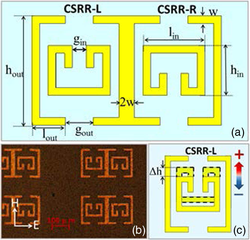
Fig. 1. (a) Structural parameters and features of Dual_CSRRs, (b) microscope image of fabricated Dual_CSRRs sample, (c) shift motion of the inner resonator in CSRR-L.
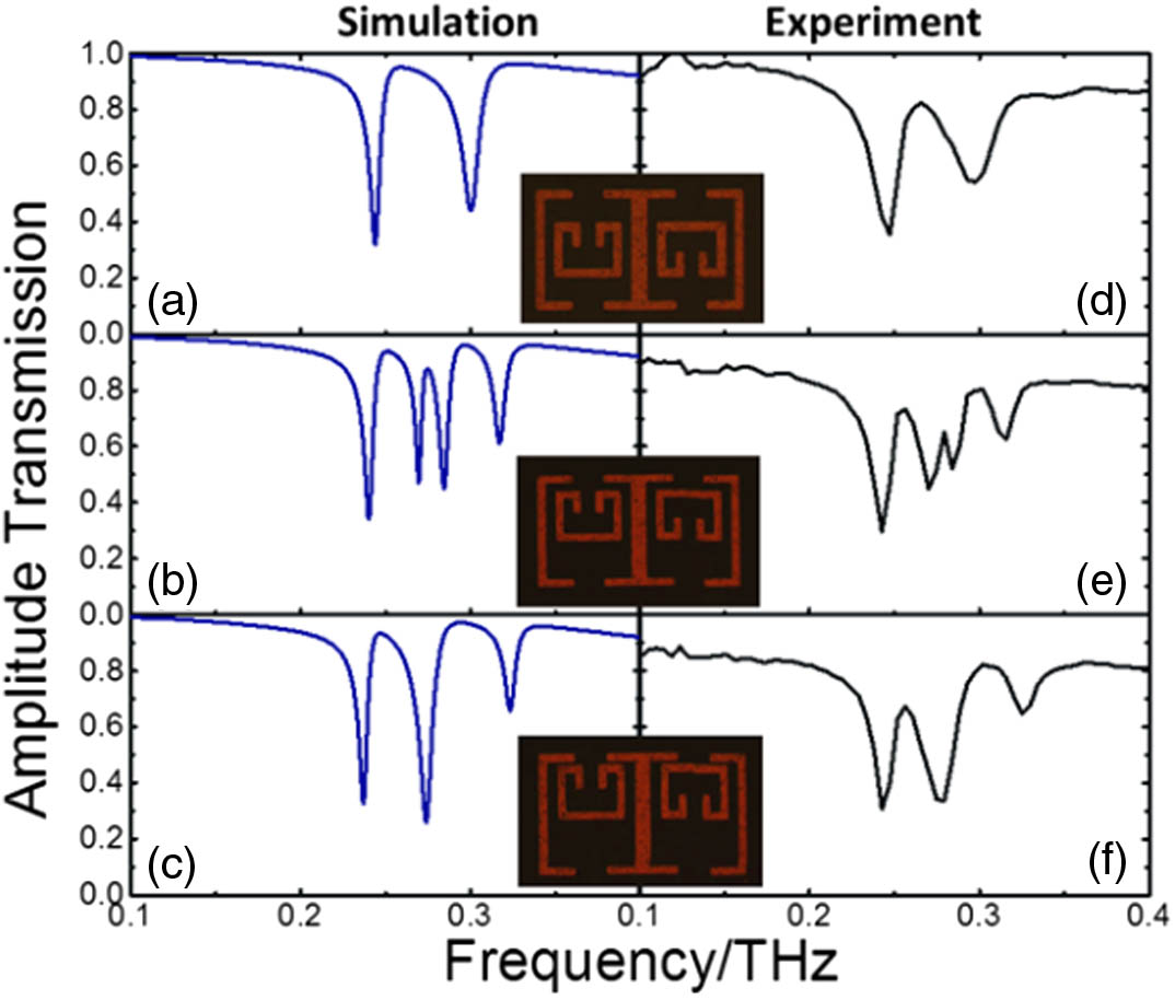
Fig. 2. Simulation and measurement results of Dual_CSRRs devices with different shifting position of SRRIs: (a–c) simulated transmission spectra of devices, (d–f) measured transmission of THz wave. The inserts from top to bottom are microscope images of the fabricated Dual_CSRRs(0,0), Dual _ CSRRs ( 30 , − 30 ) Dual _ CSRRs ( 40 , − 40 )
Fig. 3. (a) Simulation results of transmission spectra for CSRR-L with Δ h − 40 Dual _ CSRRs ( 30 , − 30 ) Dual _ CSRRs ( 40 , − 40 )
Fig. 4. (a) Simulated amplitude transmission of CSRR-L, SRRI, and SRRO. (b,c) Schematics of metamaterial unit cell for SRRI and SRRO. Electric polarization is parallel to the split gap for CSRR-L and SRRI, and simulation results with polarization along both x y
Fig. 5. Surface current and electric field distributions of devices: (a,b) surface current distributions of CSRR-L with black arrows representing the trend of surface current on SRRIs and SRROs. (c–f) Distributions of electric field for CSRR-L and Dual_CSRRs, respectively. The frequency resonance in (a), (c), and (e) is at 0.25 THz, and the frequency resonance in (b), (d), and (f) is at 0.3 THz.
Fig. 6. Simulated transmission spectrum of Dual_CSRR(40,40) when E polarization is along the x


Set citation alerts for the article
Please enter your email address

© Copyright 2018-2021 | Chinese Laser Press. All Rights Reserved 沪ICP备15018463号-20