Abstract
We propose and demonstrate a multifunctional location-dependent metamaterial in the terahertz (THz) range in which the unit cell consists of two pairs of coupled resonators. Experimental and simulation results of our devices reveal that both pairs of the coupled resonators will keep their individual resonance modes when they join together. Thus, the overall transmission spectrum is a combination of frequency response spectra of its corresponding constituent parts. While changing the locations of the inner resonators in our structure, controllable width of transmission window and changeable number of transmission dips can be realized. Our design provides a feasiblestructure for multifunctional microelectromechanical devices.1. INTRODUCTION
Recently, artificially designed metamaterials have attracted a tremendous amount of attention due to their exotic and extraordinary response to electromagnetic waves. Metamaterials are made of dense arrays of metallic micro- or nanostructures, such as split-ring resonators (SRRs), cut-wire pairs, or coupled resonators [1–4]. Among these structures, coupled resonators have been intensively reported as having fascinating properties. For example, strong near-field coupling is achieved by two orthogonally twisted concentric SRRs [5], four U-shaped resonators around a central bar resonator are designed in a metamaterial unit cell for broadband-induced transparency [6], multilayer metamaterials with split-ring resonators are carried out to achieve high-performance broadband filter [7], and two ring resonators and a split wire are made on movable substrate to realize tunable absorption peak [8]. These designs of metamaterials can be divided into two schemes: 1, planar metamaterials with their resonators arranging on the same substrate; 2, reconfigurable metamaterials with their resonators arranging on different substrates. Although under similar physical mechanisms, these two schemes of metamaterials have their own characteristics. In terms of planar metamaterials, the fabrication process is easy and their resonance frequency can be tuned by pump beam [9,10] or external electrical field [11] for modulation purposes, but the whole operation system of optical pumping is large and the On/Off ratio of external bias control is not at a high level. For reconfigurable metamaterials, the operating resonance frequency can be tuned simply by reconfiguring the relative position of the coupled resonators, but the fabrication is complicated. Compared with the former, reconfigurable metamaterials have a relatively high On/Off ratio while the whole device (or system) can be kept to a small size. Tunability of metamaterials can be realized by microelectromechanical systems (MEMS) fabrication [12,13] and actuation methods [14]. As long as MEMS fabrication is utilized, the operating frequency of many previous location-dependent metamaterials can be modulated simply [15–17]. However, changeable frequency ranges and transmission modes of these metamaterials are limited, which make it unnecessary to combine such structures with MEMS.
In this paper, we propose several designs of location-dependent metamaterials in the THz range, which can change the number of transmission dips easily with slight adjustment of relative position of coupled resonators. Such designs can be adopted for those advanced reconfiguration metamaterials based on MEMS technology, which is beneficial for the development of terahertz (THz) modulators and sensors in the future.
2. STRUCTURE AND FABRICATION
Constituent elements of our metamaterial unit cell [Fig. 1(a)] are made of two pairs of coupled subwavelength SRRs: the left concentric coupled resonator (CSRR-L) and the right concentric coupled resonator (CSRR-R). The CSRR-R is inverted relative to the CSRR-L, and they join together without any open space on the substrate. With dual coupled resonators, the metamaterial device is named Dual_CSRRs. The geometric dimensions of Dual_CSRRs are as follows: , , , , , , and . Following conventional photolithography, the copper Dual_CSRRs (1 μm thick) were fabricated on a piece of polyimide (25 μm thick) substrate, which is similar to the processes we used in previous work [10]. A microscope image of fabricated Dual_CSRRs is shown in Fig. 1(b).
Sign up for Photonics Research TOC. Get the latest issue of Photonics Research delivered right to you!Sign up now
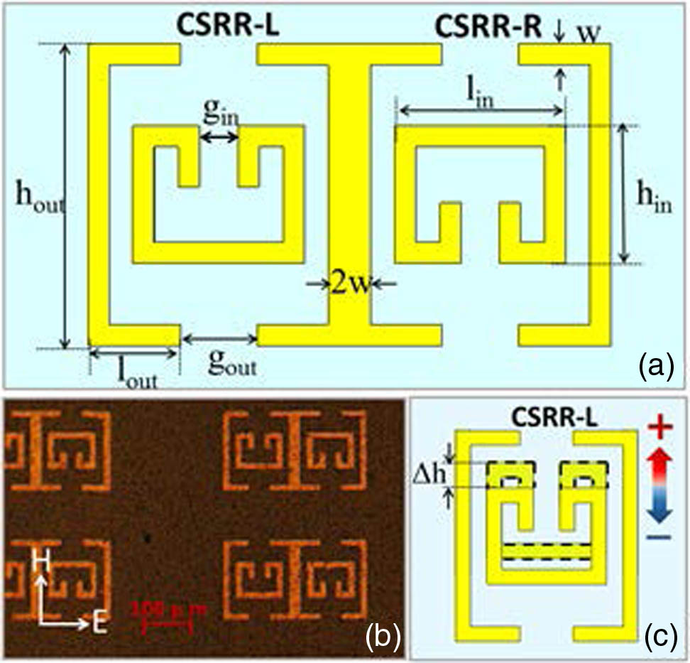
Figure 1.(a) Structural parameters and features of Dual_CSRRs, (b) microscope image of fabricated Dual_CSRRs sample, (c) shift motion of the inner resonator in CSRR-L.
To explore the characteristics of this device, the two inner resonators (SRRIs) in Dual_CSRRs were shifted. As CSRR-L and CSRR-R are inverted, with the same formation and geometric dimensions, only the CSRR-L was cut out to show movement motion of the SRRIs [as shown in Fig. 1(c)]. represents the value that SRRI has been shifted from its original position. As the red and blue arrows show in Fig. 1(c), it will be positive if SRRI is shifted upward or it will be negative if SRRI is shifted downward. Three Dual_CSRRs samples are fabricated with their SRRIs shifted up by 0, 30, and 40 μm, as shown in the inserts of Fig. 2. Obviously, of CSRR-L is 30 μm and of CSRR-R is while SRRIs are shifted up by 30 μm. Henceforth, refers to the Dual_CSRRs with SRRI shifted up by 30 μm. Similarly, refers to the Dual_CSRRs with SRRI shifted up by 40 μm.

Figure 2.Simulation and measurement results of Dual_CSRRs devices with different shifting position of SRRIs: (a–c) simulated transmission spectra of devices, (d–f) measured transmission of THz wave. The inserts from top to bottom are microscope images of the fabricated Dual_CSRRs(0,0), , and , respectively.
3. DEVICE MEASUREMENT AND MECHANISM ANALYSIS
These fabricated metamaterial samples were characterized by THz time domain spectroscopy (THz-TDS). Transmission of THz waves of our devices were measured under normal incidence with polarization of incident wave along the split gap, as shown in Fig. 1(b). A piece of bare polyimide sample was made identical to the substrate to work as a reference for these measurements. The time domain data of samples were converted into frequency-dependent amplitude by Fourier transformation to obtain normalized transmission spectra. Commercial CST Microwave Studio based on finite element method was also used to simulate these metamaterial devices to study their working mechanism.
As the simulation and experimental results show in Fig. 2, there are two transmission dips (0.247, 0.297 THz) in Dual_CSRRs(0,0). However, when the SRRIs were shifted up by 30 and 40 μm, there are four and three transmission dips in the transmission spectra, respectively. The simulation results agree well with the measurements except for a few deviations in their amplitudes and linewidths, mainly due to the measurement accuracy of our THz-TDS system and the slight differences between the parameters of material properties used in the simulation and those of real samples.
To study the relations of the number of transmission dips and the shift distance of SRRIs, the transmission spectra of a series of CSRR-Ls were investigated by simulation, with changing from to 40 μm at distance interval of 10 μm. The simulation results, as shown in Fig. 3(a), demonstrate that the transmission band of CSRR-L would continuously decrease to zero while is changed from to 40 μm. From Figs. 3(b)–3(d), it is observed that the positions and amplitudes of transmission dips in the frequency response spectra of Dual_CSRRs match with the resonance dips from their corresponding CSRR-Ls and CSRR-Rs. Therefore, when CSRR-L and CSRR-R are bonded together, they would keep their own resonance modes and the overall transmission spectrum of Dual_CSRRs is a combination of the frequency response of these separate pairs of coupled resonators.
Figure 3.(a) Simulation results of transmission spectra for CSRR-L with changing from to 40 μm, (b–d) simulated transmission spectra of Dual_CSRRs and their individual CSRR-L and CSRR-R: (b) Dual_CSRRs(0,0), (c) , (d) .
In order to further understand the physical mechanism of our proposed devices, we investigate the transmission spectra of the inner and outer resonators separately, as shown in Fig. 4(a). In particular, outer resonator (SRRO) with orientations of incident electric field parallel to the axis and axis are all simulated, but SRRI is only simulated with E polarization along the axis [Figs. 4(b) and 4(c)]. When the incident electric field is polarized along the split gap of the SRRI, fundamental inductive-capacity (LC) resonance in SRRI would be excited at 0.276 THz, while SRRO has no resonance dips in the selected frequency range when the polarization of the wave is parallel to the split gap. However, SRRO shows dipolar resonance [6] at 0.317 THz when the polarization of the incident wave is parallel to the axis. Thus, when the incident electric field is parallel to the split gaps, SRRI in CSRR-L couples with the incident electric field intensely and SRRO is excited by the electric induction derived from the SRRI. As long as surface currents are aroused around the full circumferences on both SRRI and SRRO loops [Figs. 5(a) and 5(b)], the interaction between the outer and inner resonators through electromagnetic flux would result in hybridized resonance modes [5,18]. Thus, two new resonance dips (0.255 and 0.308 THz) of CSRR-L would appear around the fundamental LC resonance of SRRI (0.276 THz). The physical mechanism of resonance modes observed in Figs. 5(a) and 5(b) is close to electromagnetic-induced transparency effect but with narrow transmission window in the frequency spectrum, which is due to the slight difference of resonance frequencies between SRRI and SRRO.
Figure 4.(a) Simulated amplitude transmission of CSRR-L, SRRI, and SRRO. (b,c) Schematics of metamaterial unit cell for SRRI and SRRO. Electric polarization is parallel to the split gap for CSRR-L and SRRI, and simulation results with polarization along both axis and axis for SRRO are presented.
Figure 5.Surface current and electric field distributions of devices: (a,b) surface current distributions of CSRR-L with black arrows representing the trend of surface current on SRRIs and SRROs. (c–f) Distributions of electric field for CSRR-L and Dual_CSRRs, respectively. The frequency resonance in (a), (c), and (e) is at 0.25 THz, and the frequency resonance in (b), (d), and (f) is at 0.3 THz.
The distributions of the electric field present that the induced electric field is mainly scattered around the split gap of the inner resonator. Therefore, when the induced electric field locates at the middle of CSRR-L [, Fig. 3(d)], great resonances would be made through electromagnetic interaction between SRRO and SRRI with the maximum amount of induced electric field in SRRO. In this circumstance, there are two separated resonance dips in the transmission spectrum. Then the bandwidth between these two dips would decrease when SRRI is shifted upward, with less and less incident electric field coupling into SRRO. Since SRRI is shifted to the top of the open space of the SRRO, there is almost no electric field going through the outer C-shaped resonators. Therefore, only one LC resonance dip (0.277 THz) would be excited by SRRI in CSRR-R, which is similar to the LC resonance dip excited by the single SRRI structure, as shown in Fig. 4(a). Moreover, the distribution of electric fields for Dual_CSRRs(0,0) can be observed in Figs. 5(e) and 5(f). The similar resonance modes of Dual_CSRRs and CSRR-L can also prove that, when two pairs of coupled resonators join together, they would keep their individual resonances.
According to the mentioned studies, we expect one resonance dip appearing in the transmission spectrum in the range 0.1 to 0.4 THz if two CSRR-L () are connected together as the insert in Fig. 6. As anticipated, the simulated transmission spectrum of Dual_CSRRs(40,40) shows only one transmission dip at 0.268 THz. This verification can further prove that the above frequencies’ combination theory of our structure is true.
Figure 6.Simulated transmission spectrum of Dual_CSRR(40,40) when E polarization is along the axis; the insert is a schematic of Dual_CSRR(40,40).
Our proposed structures can be used as a multifunction switcher when the devices are fabricated on two or more movable substrates via MEMS technology. For example, the outer resonators of Dual_CSRRs are fabricated in a fixed substrate, while all the inner resonators are made on a movable substrate. When the movable substrate is shifted up or down from its original position, the number of transmission dips would change from two to three or four. If the switcher has two independent movable substrates on which the inner resonances of CSRR-L and CSRR-R were fabricated separately, the following functions can be achieved: 1, by moving those two independent movable substrates simultaneously to keep the same for both CSRR-L and CSRR-R, a reconfigurable bandpass filter with controllable width of the transmission window can be realized [ranging from its maximum bandwidth to zero, with changing from to 40 μm like that shown in Fig. 3(a)]; 2, by moving these two independent movable substrates freely, a channel-number changeable switcher ranging from 1 to 4 can be achieved. It is worth mentioning that the situations shown in Fig. 2 are included in function 2.
4. CONCLUSION
In conclusion, we fabricate and simulate a series of location-dependent metamaterials which can achieve a different number of transmission dips through shifting the positions of the inner resonators. The simulated distributions of surface current and electric field reveal that, when CSRR-L and CSRR-R join together, they would keep their own resonance. The formation mechanism of transmission dips of Dual_CSRRs can be explained as a combination of frequency response spectra of their corresponding constituent parts (CSRR-L and CSRR-R). When the proposed location-dependent metamaterials are adopted as multifunction devices fabricated by MEMS technology, the devices can work as a reconfigurable dual-channel filter with controllable width of transmission window, or a channel-number changeable switcher which has channel numbers ranging from 1 to 4. These functions of our designs will be beneficial for the development of modulators, switchers, filters, and sensors in the future.
ACKNOWLEDGMENT
Acknowledgment. This work was supported in part by the National Natural Science Foundation of China under Grant 61205095, the Shanghai Young College Teacher Develop funding schemes under Grant slg11006, and the Leading Academic Discipline Project of Shanghai Municipal Government under Grant S30502.
References
[1] V. A. Fedotov, M. Rose, S. L. Prosvirnin, N. Papasimakis, N. I. Zheludev. Sharp trapped-mode resonances in planar metamaterials with a broken structural symmetry. Phys. Rev. Lett., 99, 147401(2007).
[2] J. Zhang, S. Xiao, C. Jeppesen, A. Kristensen, N. Asger Mortensen. Electromagnetically induced transparency in metamaterials at near-infrared frequency. Opt. Express, 18, 17187-17192(2010).
[3] S. Han, R. Singh, L. Cong, H. Yang. Engineering the fano resonance and electromagnetically induced transparency in near-field coupled bright and dark metamaterial. J. Appl. Phys., 48, 035104(2015).
[4] R. Singh, I. A. I. Al-Naib, Y. Yang, D. R. Chowdhury, W. Cao, C. Rockstuhl, T. Ozaki, R. Morandotti, W. Zhang. Observing metamaterial induced transparency in individual Fano resonators with broken symmetry. Appl. Phys. Lett., 99, 201107(2011).
[5] D. R. Chowdhury, J. F. O’Hara, A. J. Taylor, A. K. Azad. Orthogonally twisted planar concentric split ring resonators towards strong near field coupled terahertz metamaterials. Appl. Phys. Lett., 104, 101105(2014).
[6] Z. Zhu, X. Yang, J. Gu, J. Jiang, W. Yue, Z. Tian, M. Tonouchi, J. Han, W. Zhang. Broadband plasmon induced transparency in terahertz metamaterials. Nanotechnology, 24, 214003(2013).
[7] N. R. Han, Z. C. Chen, C. S. Lim, B. Ng, M. H. Hong. Broadband multi-layer terahertz metamaterials fabrication and characterization on flexible substrates. Opt. Express, 19, 6990-6998(2011).
[8] T. Yang, X. Li, W. Zhu. A tunable metamaterial absorber employing MEMS actuators in THz regime. IEEE International Conference on Nano/Micro Engineered and Molecular Systems, 829-832(2013).
[9] I. Chatzakis, L. Luo, J. Wang, N. Shen, T. Koschn, J. Zhou, C. M. Soukoulis. Reversible modulation and ultrafast dynamics of terahertz resonances in strongly photoexcited metamaterials. Phys. Rev. B, 86, 125110(2012).
[10] Y. Bai, K. Chen, H. Liu, T. Bu, B. Cai, J. Xu, Y. Zhu. Optically controllable terahertz modulator based on electro-magnetically-induced-transparency-like effect. Opt. Commun., 353, 83-89(2015).
[11] M. Liao, J. Cong, X. Zhang, Y. Cui. Development of an electrically controlled terahertz-wave modulator. J. Modern Opt., 60, 1690-1695(2013).
[12] W. M. Zhu, A. Q. Liu, W. Zhang, J. F. Tao, T. Bourouina, J. H. Teng, X. H. Zhang, Q. Y. Wu, H. Tanoto, H. C. Guo, G. Q. Lo, D. L. Kwong. Polarization dependent state to polarization independent state change in THz metamaterials. Appl. Phys. Lett., 99, 221102(2011).
[13] Y. H. Fu, A. Q. Liu, W. M. Zhu, X. M. Zhang, D. P. Tsai, J. B. Zhang, T. Mei, J. F. Tao, H. C. Guo, X. H. Zhang, J. H. Teng, N. I. Zheludev, G. Q. Lo, D. L. Kwong. A micromachined reconfigurable metamaterial via reconfiguration of asymmetric split-ring resonators. Adv. Funct. Mater., 21, 3589-3594(2011).
[14] W. Zhang, A. Q. Liu, W. M. Zhu, E. P. Li, H. Tanoto, Q. Y. Wu, J. H. Teng, X. H. Zhang, M. L. J. Tsai, G. Q. Lo. Micromachined switchable metamaterial with dual resonance. Appl. Phys. Lett., 101, 151902(2012).
[15] A. E. Çetin, A. Artar, M. Turkmen, A. A. Yanik, H. Altug. Plasmon induced transparency in cascaded π-shaped metamaterials. Opt. Express, 19, 22607-22618(2011).
[16] D. R. Chowdhury, N. Xu, W. Zhang, R. Singh. Resonance tuning due to Coulomb interaction in strong near-field coupled metamaterials. J. Appl. Phys., 118, 023104(2015).
[17] B. Wang, L. Wang, G. Wang, W. Huang, X. Zhai, X. Li. Tunable bandwidth of the terahertz metamaterial absorber. Opt. Commun., 325, 78-83(2014).
[18] E. Prodan, C. Radloff, N. J. Halas, P. Nordlander. A hybridization model for the plasmon response of complex nanostructures. Science, 302, 419-422(2003).

