• Laser & Optoelectronics Progress
  • Vol. 59, Issue 14, 1415007 (2022)
Xingsheng Liu1、†, Anhu Li†、*, Zhaojun Deng, and Hao Chen
Author Affiliations
  • School of Mechanical Engineering, Tongji University, Shanghai 201804, China
  • show less
    DOI: 10.3788/LOP202259.1415007 Cite this Article Set citation alerts
    Xingsheng Liu, Anhu Li, Zhaojun Deng, Hao Chen. Advances in Three-Dimensional Imaging Technologies Based on Single-Camera Stereo Vision[J]. Laser & Optoelectronics Progress, 2022, 59(14): 1415007 Copy Citation Text show less
    Camera model with definition of coordinate systems
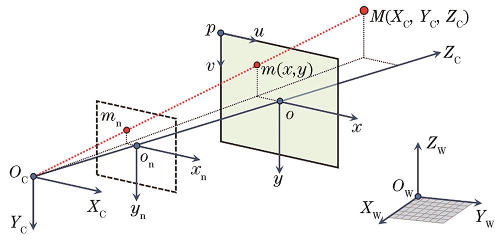
    Fig. 1. Camera model with definition of coordinate systems
    Multiview geometry model. (a) Multiview imaging with stereo correspondences; (b) space resection among backward projection rays
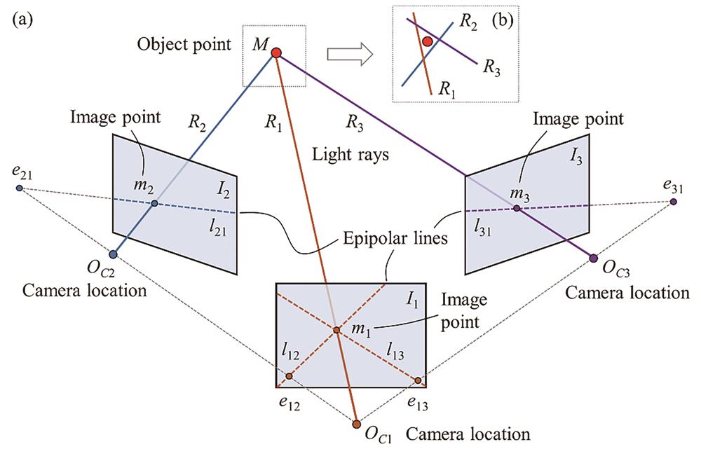
    Fig. 2. Multiview geometry model. (a) Multiview imaging with stereo correspondences; (b) space resection among backward projection rays
    Structure from motion problem [29]
    Fig. 3. Structure from motion problem [29]
    Integral photography proposed by Lippmann[17]. (a) Basic imaging principle; (b) light field sampling mode
    Fig. 4. Integral photography proposed by Lippmann[17]. (a) Basic imaging principle; (b) light field sampling mode
    3D integral imaging based on axially distributed sensing [53]. (a) Pickup strategy for elemental images; (b) reconstructed images at different depths
    Fig. 5. 3D integral imaging based on axially distributed sensing [53]. (a) Pickup strategy for elemental images; (b) reconstructed images at different depths
    3D integral imaging based on off-axially distributed sensing[56]. (a) Pickup strategy for elemental images; (b) two elemental images with object occlusion and 3D reconstructed slice images
    Fig. 6. 3D integral imaging based on off-axially distributed sensing[56]. (a) Pickup strategy for elemental images; (b) two elemental images with object occlusion and 3D reconstructed slice images
    3D integral imaging based on planar camera motion[59]. (a) Pickup strategy for elemental images; (b) reconstructed image for “car” object; (c) reconstructed image for “signal” object
    Fig. 7. 3D integral imaging based on planar camera motion[59]. (a) Pickup strategy for elemental images; (b) reconstructed image for “car” object; (c) reconstructed image for “signal” object
    3D imaging system structure with a set of planar mirrors. (a) One mirror [62]; (b) two mirrors [64]; (c) three mirrors [66]; (d) four mirrors [68]
    Fig. 8. 3D imaging system structure with a set of planar mirrors. (a) One mirror [62]; (b) two mirrors [64]; (c) three mirrors [66]; (d) four mirrors [68]
    3D profile and deformation measurement method combining four-mirror-based 3D imaging system with digital image correlation technique [72]
    Fig. 9. 3D profile and deformation measurement method combining four-mirror-based 3D imaging system with digital image correlation technique [72]
    Dynamic 3D imaging method combining four-mirror catadioptric system with a pan-tilt mirror [74]. (a) Optical arrangement; (b) 3D tracking and imaging for a dynamic object
    Fig. 10. Dynamic 3D imaging method combining four-mirror catadioptric system with a pan-tilt mirror [74]. (a) Optical arrangement; (b) 3D tracking and imaging for a dynamic object
    3D imaging methods using curved mirrors. (a)-(c) System with two oppositely configured hyperboloidal mirrors, panoramic image captured by system, and 3D reconstruction results[77]; (d)-(e) system with an array of spherical mirrors, and 3D reconstructed images[79]
    Fig. 11. 3D imaging methods using curved mirrors. (a)-(c) System with two oppositely configured hyperboloidal mirrors, panoramic image captured by system, and 3D reconstruction results[77]; (d)-(e) system with an array of spherical mirrors, and 3D reconstructed images[79]
    3D stereo imaging technique using a biprism. (a)-(c) 3D measurement principle based on modified virtual point model, system structure and measurement error map [82]; (d)-(f) 3D reconstruction principle based on perspective projection model, system structure and reconstructed object [83]
    Fig. 12. 3D stereo imaging technique using a biprism. (a)-(c) 3D measurement principle based on modified virtual point model, system structure and measurement error map [82]; (d)-(f) 3D reconstruction principle based on perspective projection model, system structure and reconstructed object [83]
    Stereo endoscopic imaging method using microprism arrays[89]. (a) System setup; (b) 3D imaging model; (c) prototype of microprism array and system; (d) reconstructed depth maps for an object at different distances
    Fig. 13. Stereo endoscopic imaging method using microprism arrays[89]. (a) System setup; (b) 3D imaging model; (c) prototype of microprism array and system; (d) reconstructed depth maps for an object at different distances
    3D imaging with an optically transparent plate. (a)-(c) System setup, depth estimation maps, and 3D reconstructed images[92]; (c)-(f) system setup with a MEMS-driven plate, rectified image, and depth map[93]
    Fig. 14. 3D imaging with an optically transparent plate. (a)-(c) System setup, depth estimation maps, and 3D reconstructed images[92]; (c)-(f) system setup with a MEMS-driven plate, rectified image, and depth map[93]
    3D imaging using a rotational wedge prism[95]. (a) System structure; (b) imaging model; (c) multiview stereo image matching; (d) 3D profile reconstruction; (e) 3D scale reconstruction
    Fig. 15. 3D imaging using a rotational wedge prism[95]. (a) System structure; (b) imaging model; (c) multiview stereo image matching; (d) 3D profile reconstruction; (e) 3D scale reconstruction
    3D information acquisition based on diffraction grating. (a) 3D digital image correlation measurement system for 3D displacement reconstruction [100]; (b) 3D diffraction-assisted fluorescent microscopy for 3D displacement reconstruction [101]
    Fig. 16. 3D information acquisition based on diffraction grating. (a) 3D digital image correlation measurement system for 3D displacement reconstruction [100]; (b) 3D diffraction-assisted fluorescent microscopy for 3D displacement reconstruction [101]
    3D integral imaging using a diffraction grating[106]. (a) Diffraction-grating-based image capture and computational reconstruction under multi-wavelength laser illumination; (b) 3D reconstructed images from parallax image arrays obtained with different wavelengths
    Fig. 17. 3D integral imaging using a diffraction grating[106]. (a) Diffraction-grating-based image capture and computational reconstruction under multi-wavelength laser illumination; (b) 3D reconstructed images from parallax image arrays obtained with different wavelengths
    Calibration of 3D imaging system using planar mirrors[109]. (a) Respective calibration for two virtual cameras; (b) direct calibration for system parameters.
    Fig. 18. Calibration of 3D imaging system using planar mirrors[109]. (a) Respective calibration for two virtual cameras; (b) direct calibration for system parameters.
    Calibration of 3D imaging system using a conic mirror[111]. (a) Conic mirror structure with multiple control points on mirror base; (b) a calibration image with control points captured by system
    Fig. 19. Calibration of 3D imaging system using a conic mirror[111]. (a) Conic mirror structure with multiple control points on mirror base; (b) a calibration image with control points captured by system
    Model-free distortion correction method for biprism-based 3D imaging system[112]
    Fig. 20. Model-free distortion correction method for biprism-based 3D imaging system[112]
    Calibration method for rotational-prism-based variable-boresight 3D imaging system[116]
    Fig. 21. Calibration method for rotational-prism-based variable-boresight 3D imaging system[116]
    CategoryOptical elementView divisionStrengthShortcoming
    ReflectionPlanar mirrors62-69SpaceSimple setup,free from distortion,synchronous image acquisitionReduced field of view and spatial resolution
    Planar mirrors and pan-tilt mirror74Space & TimeWide field of view,fast dynamic response,multiview acquisitionComplexity in hardware and control,sensitivity to random error sources
    Curved mirrors75-78SpaceOmnidirectional stereoComplicated mirror design,limited spatial resolution
    Multi-mirror array79SpaceOmnidirectional stereo,multiview acquisitionTradeoff between field of view and resolution
    RefractionBiprism80-83SpaceCompact structure,viewpoint symmetry,image synchronizationBiprism distortion,certain perspective,limited field of view
    Microprism array87-89SpaceLight weight,miniaturizationIncreased cost on micro design and fabrication
    Transparent plate91-93TimeHigh-resolution multiview acquisitionRequiring plate rotation,small stereo baseline,limited disparity range
    Wedge prism95-97TimeCost-effective setup,flexible perspective,extended field of viewRequiring prism rotation,increased time for multiview acquisition
    DiffractionGrating under monochromatic illumination98-102SpaceStereoscopic image acquisition,high-accuracy reconstructionRequiring illumination,limited to micro or small objects
    Grating under multi-wavelength illumination106Space & TimeMulti-spectrum image acquisition,enhanced 3D reconstruction qualityRequiring illumination,more time cost for image collection
    Table 1. Comparison of 3D imaging methods using various additional optical elements
    Xingsheng Liu, Anhu Li, Zhaojun Deng, Hao Chen. Advances in Three-Dimensional Imaging Technologies Based on Single-Camera Stereo Vision[J]. Laser & Optoelectronics Progress, 2022, 59(14): 1415007
    Download Citation