• Photonics Research
  • Vol. 2, Issue 4, B80 (2014)
Yamei Zhang, Fangzheng Zhang, and and Shilong Pan*
Author Affiliations
  • Key Laboratory of Radar Imaging and Microwave Photonics, Ministry of Education, Nanjing University of Aeronautics and Astronautics, Nanjing 210016, China
  • show less
    DOI: 10.1364/PRJ.2.000B80 Cite this Article Set citation alerts
    Yamei Zhang, Fangzheng Zhang, and Shilong Pan. Optical single sideband polarization modulation for radio-over-fiber system and microwave photonic signal processing[J]. Photonics Research, 2014, 2(4): B80 Copy Citation Text show less
    Schematic diagram of the proposed configuration to implement OSSB polarization modulation. OSA, optical spectrum analyzer.
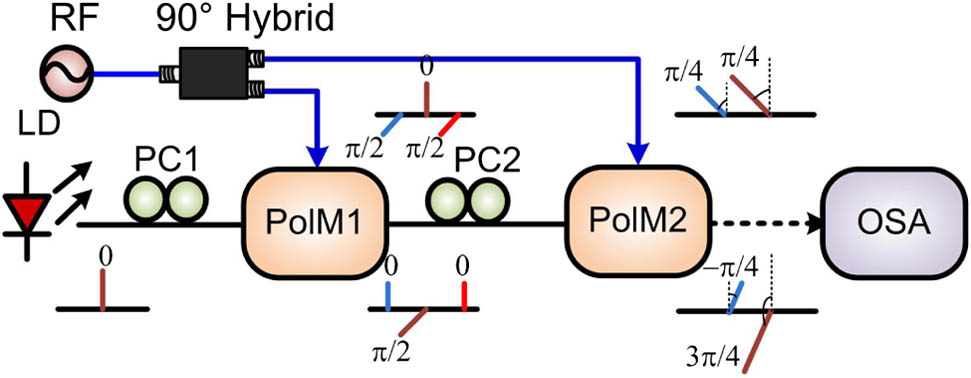
    Fig. 1. Schematic diagram of the proposed configuration to implement OSSB polarization modulation. OSA, optical spectrum analyzer.
    (a) Optical spectrum of the generated OSSB polarization-modulated signal after PolM2 and (b) sideband suppression ratios of the OSSB modulated signals when the frequency of the RF signal is varied from 12.5 to 35 GHz.
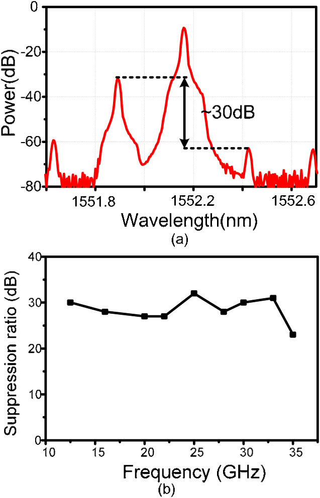
    Fig. 2. (a) Optical spectrum of the generated OSSB polarization-modulated signal after PolM2 and (b) sideband suppression ratios of the OSSB modulated signals when the frequency of the RF signal is varied from 12.5 to 35 GHz.
    Sideband suppression ratios of the OSSB polarization-modulated signal when γ1=0.4488 while γ2 changes from 0 to 3.
    Fig. 3. Sideband suppression ratios of the OSSB polarization-modulated signal when γ1=0.4488 while γ2 changes from 0 to 3.
    Sideband suppression ratios of the OSSB modulated signals when the phase difference between the two electrical drive signals changes from 0° to 180°.
    Fig. 4. Sideband suppression ratios of the OSSB modulated signals when the phase difference between the two electrical drive signals changes from 0° to 180°.
    Electrical spectra (a) when the OSSB signal is directed straight to the PD and (b) when a polarizer is inserted before the PD.
    Fig. 5. Electrical spectra (a) when the OSSB signal is directed straight to the PD and (b) when a polarizer is inserted before the PD.
    Optical spectra of the OSSB polarization-modulated signals at different wavelengths.
    Fig. 6. Optical spectra of the OSSB polarization-modulated signals at different wavelengths.
    Electrical spectra and constellation diagrams of (a), (b) input and output 10 GHz microwave signal with 50 Mbaud 16 QAM baseband data after (c), (d) 25 km and (e), (f) 50 km fiber transmission.
    Fig. 7. Electrical spectra and constellation diagrams of (a), (b) input and output 10 GHz microwave signal with 50 Mbaud 16 QAM baseband data after (c), (d) 25 km and (e), (f) 50 km fiber transmission.
    Schematic diagram of the microwave photonic phase shifter based on the proposed OSSB PolM. Pol, polarizer.
    Fig. 8. Schematic diagram of the microwave photonic phase shifter based on the proposed OSSB PolM. Pol, polarizer.
    Phase responses of the microwave photonic phase shifter based on the proposed OSSB PolM when the frequency changes.
    Fig. 9. Phase responses of the microwave photonic phase shifter based on the proposed OSSB PolM when the frequency changes.
    Yamei Zhang, Fangzheng Zhang, and Shilong Pan. Optical single sideband polarization modulation for radio-over-fiber system and microwave photonic signal processing[J]. Photonics Research, 2014, 2(4): B80
    Download Citation