Abstract
An approach to implementing optical single sideband (OSSB) polarization modulation, which is a combination of two orthogonally polarized OSSB modulations with complementary phase differences between the optical carrier and the sideband, is demonstrated based on two cascaded polarization modulators (PolMs). The two PolMs are driven by two RF signals that are 90° out of phase. By properly adjusting the polarization state between the two PolMs, OSSB polarization modulation with large operation bandwidth can be realized. An experiment is performed. OSSB polarization modulation with an operation bandwidth from 2 to 35 GHz is successfully demonstrated. The spectral profile of the OSSB polarization-modulated signal is observed through an optical spectrum analyzer, and its complementary phase properties are analyzed by sending the signal to a photodetector (PD) for square-law detection. Due to the complementary phase differences between the optical carrier and the sideband along the two polarization directions, no microwave frequency component is generated after the PD. The generated OSSB polarization-modulated signal is transmitted through 25 and 50 km single-mode fiber with 50 Mbaud 16 quadrature amplitude modulation baseband data to investigate the transmission performance of the proposed system in radio-over-fiber applications, and very small error vector magnitude degradation is observed. OSSB polarization modulation is also employed to realize a microwave photonic phase shifter. A full-range tunable phase shift is obtained for 2 and 35 GHz microwave signals.1. INTRODUCTION
Radio-over-fiber (ROF) technology has attracted a lot of attentions thanks to its capability for low-loss transmission of microwave/millimeter-wave signals over broadband optical fibers [1–3]. Optical single sideband (OSSB) modulation is regarded as one of the most promising techniques to deal with chromatic dispersion-induced power fading and improve the spectral efficiency in ROF systems [4]. Many methods have been proposed to implement OSSB modulation over the past few decades [5–17]. For instance, OSSB modulation can be realized by using a single sideband modulator, which can be a dual-drive Mach–Zehnder modulator (MZM) [5,6], four parallel phase modulators [7,8], a hybrid modulator consisting of an amplitude modulator and a phase modulator [9], two parallel electro-absorption modulators (EAMs) [10], or a bidirectional intensity modulator placed inside a Sagnac interferometer (SI) [11]. By carefully controlling the phase difference between the input RF signals (usually ), one of the first-order sidebands can be suppressed. OSSB modulation can also be achieved by passing a double sideband (DSB) signal through an optical filter [13–17]. In this approach, a DSB signal is first generated by intensity or phase modulating an optical carrier with an electrical RF signal. An optical filter, which can be a fiber Bragg grating (FBG) [13–15], a stimulated Brillouin scattering (SBS) based filter [16], or a ring resonator [17], is followed to remove one of the first-order sidebands.
However, the above methods can only achieve OSSB modulation along a single polarization direction. Recently, a concept called OSSB polarization modulation is proposed [18], which is actually a combination of two complementary OSSB modulations along the two orthogonal polarization axes; i.e., the subtraction of the phase differences between the optical carrier and the remaining sideband along the two orthogonal polarization axes is 180°. OSSB polarization modulation has been demonstrated with more flexibilities over the conventional single-polarization OSSB modulation [18–24]. For example, in [18], the OSSB polarization-modulated signal is sent into a length of polarization maintaining fiber (PMF) to introduce different time delays along the two principal axes, based on which an ultrawideband (UWB) microwave photonic filter (MPF) is constructed and used in a UWB signal generator. In [19], by introducing a 90° phase shift to one principal axis of the OSSB polarization-modulated signals and then combining the two orthogonally polarized OSSB signals with a tunable polarizer, a microwave photonic phase shifter is obtained, which features full-range tunability, flat magnitude response, large operation bandwidth, and the potential for high-speed tuning. Based on the microwave photonic phase shifter in [19], a high-speed photonic microwave phase coding system [20], a complex-coefficient MPF [21–23], and an optically controlled beamforming network [24] are successfully demonstrated.
Previously, OSSB polarization modulation was realized by using a polarization modulator (PolM) and a FBG-based notch filter [18] or a tunable optical band-pass filter (OBPF) [19–24]. The PolM produces two orthogonally polarized DSB signals with complementary phase modulations, and then the optical filter removes one of the first-order sidebands. The main drawback of this method is the high dependence on the wavelength of the optical carrier; i.e., strict alignment between the laser wavelength and the optical filtering window is required. In addition, if a wideband optical filter is used, it is difficult to remove one first-order sideband without affecting the optical carrier, while large-bandwidth OSSB polarization modulation cannot be achieved if a narrow-bandwidth optical filter is applied.
Sign up for Photonics Research TOC. Get the latest issue of Photonics Research delivered right to you!Sign up now
In this paper, a configuration for implementing OSSB polarization modulation with a large operation bandwidth is demonstrated based on two cascaded PolMs. By applying a pair of orthogonal microwave signals to the two PolMs and controlling the polarization states between the two PolMs, a broadband OSSB polarization modulation in the frequency range from 2 to 35 GHz is realized. The undesirable first-order sideband is suppressed by 30 dB as compared to the remaining one. The performance of the proposed OSSB PolM is evaluated in an ROF link. A microwave photonic phase shifter is also built based on the OSSB PolM to verify the successful implementation of OSSB polarization modulation as well as to explore the potential applications of OSSB polarization modulation in microwave photonic signal processing.
2. PRINCIPLE
Figure 1 shows a schematic diagram of the proposed OSSB polarization modulation scheme based on two cascaded PolMs. The system consists of a laser diode (LD), two polarization controllers (PCs), and two PolMs. A continuous wave (CW) lightwave from the LD is fed into the PolM via a PC (PC1). The PolM is a special phase modulator that supports both TE and TM modes with opposite phase modulation indices [19]. By adjusting PC1, the polarization direction of the lightwave sent into PolM1 has an angle of 45° to one principal axis of PolM1. Suppose the expression of the input lightwave is , and that of the RF driving signal is , where and are the angular frequencies of the optical carrier and the RF signal, respectively, and is the amplitude of the electrical drive signal; the two complementary phase-modulated optical signals generated at the output of PolM1 can be expressed by where is the phase modulation index and is the phase difference between the two principal axes of PolM1, which can be controlled by adjusting the PC before the PolM. Let be equal to ; based on the Jacobi–Anger expansions, Eq. (1) can be written as where is the th-order Bessel function of the first kind. In writing Eq. (2), small-signal modulation is assumed so that the higher-order () sidebands are ignored. Then, another PC (PC2) is used to rotate the polarization state of the output signal from PolM1 by 45°. The optical signal after PC2 is given by
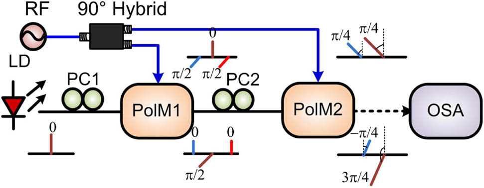
Figure 1.Schematic diagram of the proposed configuration to implement OSSB polarization modulation. OSA, optical spectrum analyzer.
After that, the optical signal is coupled into the second PolM (PolM2), of which the principal axes are aligned with those of PolM1. If PolM2 is driven by the RF signal of , i.e., the signal is 90° out of phase with that applied to PolM1, the optical signal after PolM2 is then written as where is the phase modulation index of PolM2. By controlling the input powers of the two RF signals to let , Eq. (4) becomes
As can be seen from Eq. (5), the st-order sidebands along the two orthogonal polarization directions are suppressed, indicating that OSSB modulation is performed along each polarization direction. Also from Eq. (5), the phase difference between the optical carrier and the remaining sideband is zero in one polarization direction, while the phase difference is 180° in the other polarization direction, which means the two OSSB modulations along the two orthogonal polarization axes are complementary. As a result, OSSB polarization modulation is successfully implemented. The insets of Fig. 1 illustrate the spectra of the optical signals at different positions of the proposed OSSB PolM.
3. EXPERIMENT RESULTS AND DISCUSSION
An experiment based on the setup shown in Fig. 1 is carried out. A CW light at 1552.16 nm from an LD (Agilent, N7714A) is sent to two PolMs (Versawave Inc.). The PolMs have a bandwidth of 40 GHz and a half-wave voltage of 3.5 V. An RF signal from a vector signal generator (Agilent E8267D) is divided by a broadband electrical 90° hybrid (1.7–36 GHz) into two parts, and applied to the two RF ports of the two PolMs, respectively. The optical spectra are observed by an optical spectrum analyzer (OSA, AQ6370C) with a resolution of 0.02 nm, and the electrical spectra are observed by a 43 GHz electrical spectrum analyzer (ESA, Agilent N9030A).
Figure 2(a) shows the optical spectrum of the generated OSSB polarization-modulated signal when two orthogonal 33 GHz RF signals are introduced to the two PolMs, respectively. From Fig. 2(a), it is obtained that the sideband suppression ratio is about 30 dB; i.e., the suppressed st-order sideband is 30 dB lower than the st-order sideband. The proposed OSSB polarization modulation has a very broad operation bandwidth, which is only limited by the bandwidth of the 90° hybrid (1.7–36 GHz). In the experiment, OSSB polarization-modulated optical spectra can be observed when the RF frequency changes from 2 and 35 GHz. However, when the RF frequency is lower than 10 GHz, the sideband suppression ratio cannot be clearly observed in the optical spectrum due to the limited resolution of the OSA (0.02 nm). When the RF frequency increases from 12.5 to 35 GHz, the sideband suppression ratio can be obtained through the OSSB polarization-modulated optical spectra, and the results are shown in Fig. 2(b). As can be seen, the sideband suppression ratios are larger than 25 dB except for the RF frequency of 35 GHz. The lower sideband suppression ratio for the 35 GHz RF signal is mainly due to the unbalanced output power and not exact 90° phase difference between the two outputs of the electrical hybrid at 35 GHz, as will be discussed later.

Figure 2.(a) Optical spectrum of the generated OSSB polarization-modulated signal after PolM2 and (b) sideband suppression ratios of the OSSB modulated signals when the frequency of the RF signal is varied from 12.5 to 35 GHz.
Since the RF powers applied to the two PolMs are usually unequal due to the imperfection of the electrical 90° hybrid, the two modulation indices of the two PolMs may be not the same, which will result in a low sideband suppression ratio of the OSSB polarization-modulated signal. To evaluate the impact of the modulation indices of the two PolMs on the sideband suppression ratio, the modulation index of PolM1 () is fixed to be 0.4488 (as the half-wave voltages of the PolMs are 3.5 V and the voltage of the input RF signal is 1 V), while the modulation index of PolM2 () is changed from 0 to 3. Figure 3 shows the calculated suppression ratios. As can be seen, when the two modulation indices are the same, a large suppression ratio can be obtained. In addition, from the inset of Fig. 3 we can see that when is in the range from 0.375 to 0.54, the sideband suppression ratio is larger than 20 dB, which means that, when the difference between the modulation indices of two PolMs is smaller than 0.165, the sideband suppression ratios of the OSSB polarization-modulated signal are still greater than 20 dB. When is set to other values, similar rules are acquired.
Figure 3.Sideband suppression ratios of the OSSB polarization-modulated signal when while changes from 0 to 3.
The impact of the nonideal phase difference between the outputs of the 90° hybrid is also investigated. A simulation is carried out when the power of the RF source is 6 dBm and the hybrid has an ideal 50:50 power splitting ratio without insertion loss. Figure 4 shows the calculated sideband suppression ratios of the generated OSSB modulated signals when the phase difference between the two drive signals is changed from 0° to 180°. As can be seen, to maintain a 20 dB suppression ratio, the phase difference must be in the range from 78° to 102°. To obtain a high sideband suppression ratio, the phase difference between the two RF drive signals should be carefully adjusted to be around 90°.
Figure 4.Sideband suppression ratios of the OSSB modulated signals when the phase difference between the two electrical drive signals changes from 0° to 180°.
To verify the phase properties of the OSSB polarization-modulated signal, the optical signal from PolM2 is converted to the electrical domain and analyzed by the ESA. In Eq. (5), the phase differences between the optical carrier and the sideband are 0 and for the signals along the two polarization directions, respectively. Thus, when the optical signal is sent to a photodetector (PD) for square-law detection, two complementary microwave signals at the same frequency will be generated and cancelled with each other at the output of the PD. As a result, no microwave signal will be observed. Figure 5(a) shows the electrical spectrum of the directly detected OSSB polarization-modulated signal when the frequency of the RF signal is 15 GHz. As predicted before, no frequency component at 15 GHz is observed. When a polarizer is connected to the proposed OSSB PolM to select the optical signal along a certain polarization direction, a strong 15 GHz component is observed after photodetection, as shown in Fig. 5(b). Thus, the complementary OSSB modulations along the two orthogonal polarization directions are confirmed.
Figure 5.Electrical spectra (a) when the OSSB signal is directed straight to the PD and (b) when a polarizer is inserted before the PD.
The proposed OSSB PolM features a large operation wavelength range, which is only limited by the working wavelength of the system devices. To illustrate this property, experiments are carried out to implement the OSSB polarization modulation with the optical carrier wavelength from 1565 to 1530 nm with a step of . Figure 6 shows the optical spectra of the generated OSSB polarization-modulated signals at different wavelengths when the RF frequency is 12.5 GHz. The OSSB polarization modulation is successfully obtained for all the wavelengths, and almost the same spectral profiles are obtained. The sideband suppression ratios are also about 30 dB, indicating that the OSSB polarization modulation system is wavelength independent in 1530–1565 nm. The wavelength-independent feature would allow the OSSB polarization modulation to be used for multichannel signal processing based on wavelength division multiplexing technologies.
Figure 6.Optical spectra of the OSSB polarization-modulated signals at different wavelengths.
To explore the potential application of the OSSB polarization modulation in ROF systems, the transmission performance of the generated OSSB polarization-modulated signal is investigated over 25 and 50 km single-mode fiber (SMF). A 10 GHz microwave signal carrying 50 Mbaud 16 quadrature amplitude modulation (QAM) baseband data is applied to the two PolMs to generate an OSSB polarization-modulated signal. The obtained signal is then transmitted over a section of SMF. Figures 7(a) and 7(b) show the electrical spectrum and the constellation diagram of the RF signal generated by the vector signal generator. The error vector magnitude (EVM) evaluated by 1000 symbols is 3.17%. After transmission through 25 km SMF, the electrical spectrum and the constellation diagram of the received signal are shown in Figs. 7(c) and 7(d), respectively. The EVM is 3.51%, indicating that only very small distortion is introduced after fiber transmission. The results for 50 km SMF transmission are shown in Figs. 7(e) and 7(f). The EVM is measured to be 5.01%. Compared with Figs. 7(a) and 7(c), the electrical spectrum in Fig. 7(e) has no evident distortion except for power attenuation. Moreover, the proposed OSSB polarization modulation can be used to generate OSSB modulation with a tunable optical carrier to sideband suppression ratio [25], which is useful for optimizing the transmission performance of a ROF link [26]. Therefore, OSSB polarization modulation has more applications in future ROF applications.
Figure 7.Electrical spectra and constellation diagrams of (a), (b) input and output 10 GHz microwave signal with 50 Mbaud 16 QAM baseband data after (c), (d) 25 km and (e), (f) 50 km fiber transmission.
The proposed OSSB polarization modulation also has many applications in microwave photonic signal processing systems. First, the demonstration of a microwave photonic phase shifter based on the proposed OSSB polarization modulation is performed. A schematic diagram of the microwave photonic phase shifter is shown in Fig. 8, where a polarizer is connected to the proposed OSSB PolM to combine the two orthogonally polarized components with a polarization direction of . According to [19], the output signal after the polarizer can be expressed as
Figure 8.Schematic diagram of the microwave photonic phase shifter based on the proposed OSSB PolM. Pol, polarizer.
After optical-to-electrical conversion by a PD, the obtained current is
In Eq. (7), the phase of the microwave signal can be continuously tuned by adjusting the polarization direction of the polarizer. If it changes over a 180° range, the phase shift will be varied in a range of 0°–360°. In the experiment, a PC and a polarization beam splitter (PBS) are employed as a polarizer, and the extinction ratio of the PBS is larger than 35 dB. Figure 9 shows the measured phase responses of the microwave photonic phase shifter when the frequency of the input RF signal changes from 2 to 35 GHz. As can be seen, phase shifts from to 180° are obtained for all the RF frequencies. The working bandwidth of this microwave photonic phase shifter is also limited by the 90° hybrid coupler. Compared with the demonstration in [19], the operation bandwidth of the phase shifter is extended based on the proposed OSSB PolM; i.e., the lower bound of the operation frequency is decreased to (as compared to 11 GHz in [19]). Besides, the operation is significantly simplified because no alignment of the wavelengths of the laser and the optical filter is needed, which also improves the stability of the system. This microwave photonic phase shifter can be employed to many other microwave photonic signal processing applications, such as the MPF, the optically controlled beamformer, and the phase-coded signal generator [19–24].
Figure 9.Phase responses of the microwave photonic phase shifter based on the proposed OSSB PolM when the frequency changes.
4. CONCLUSION
A novel approach to realizing OSSB polarization modulation was demonstrated based on two cascaded PolMs. Since highly wavelength dependent optical filters are avoided in the proposed scheme, a large operation bandwidth can be obtained. OSSB polarization modulation with an operation bandwidth from 2 to 35 GHz and a sideband suppression ratio of about 30 dB was experimentally implemented. The transmission performance of the generated OSSB polarization-modulated signals was also investigated in 25 and 50 km SMF links, and no evident degradation was observed. A microwave photonic phase shifter based on the proposed OSSB PolM was demonstrated. Full-range tunable phase shifts were obtained. The scheme may find applications in microwave photonic signal generation and processing.
References
[1] J. Yao. Microwave photonics. J. Lightwave Technol., 27, 314-335(2009).
[2] J. Capmany, D. Novak. Microwave photonics combines two worlds. Nat. Photonics, 1, 319-330(2007).
[3] K.-I. Kitayama. Architectural considerations of fiber-radio millimeter-wave wireless access systems. Fiber Integr. Opt., 19, 167-186(2000).
[4] K.-I. Kitayama. Highly spectrum efficient OFDM/PDM wireless networks by using optical SSB modulation. J. Lightwave Technol., 16, 969-976(1998).
[5] G. Smith, D. Novak, Z. Ahmed. Technique for optical SSB generation to overcome dispersion penalties in fibre-radio systems. Electron. Lett., 33, 74-75(1997).
[6] T. Kawanishi, M. Izutsu. Linear single-sideband modulation for high-SNR wavelength conversion. IEEE Photon. Technol. Lett., 16, 1534-1536(2004).
[7] M. Izutsu, S. Shikama, T. Sueta. Integrated optical SSB modulator/frequency shifter. IEEE J. Quantum Electron., 17, 2225-2227(1981).
[8] S. Shimotsu, S. Oikawa, T. Saitou, N. Mitsugi, K. Kubodera, T. Kawanishi, M. Izutsu. Single side-band modulation performance of a LiNbO3 integrated modulator consisting of four-phase modulator waveguides. IEEE Photon. Technol. Lett., 13, 364-366(2001).
[9] B. Davies, J. Conradi. Hybrid modulator structures for subcarrier and harmonic subcarrier optical single sideband. IEEE Photon. Technol. Lett., 10, 600-602(1998).
[10] M. Zhou, A. Sharma, Z. Shao, M. Fujise. Optical single-sideband modulation at 60 GHz using electro-absorption modulators. International Topical Meeting on Microwave Photonics, 121-124(2005).
[11] A. Loayssa, R. Hernández, D. Benito. Optical single-sideband modulators and their applications. Fiber Integr. Opt., 23, 171-188(2004).
[12] J. Park, W. Sorin, K. Lau. Elimination of the fibre chromatic dispersion penalty on 1550 nm millimeter-wave optical transmission. Electron. Lett., 33, 512-513(1997).
[13] S. Blais, J. Yao. Optical single sideband modulation using an ultranarrow dual-transmission-band fiber Bragg grating. IEEE Photon. Technol. Lett., 18, 2230-2232(2006).
[14] J. Capmany, B. Ortega, A. Martinez, D. Pastor, M. Popov, P. Y. Fonjallaz. Multiwavelength single sideband modulation for WDM radio-over-fiber systems using a fiber grating array tandem device. IEEE Photon. Technol. Lett., 17, 471-473(2005).
[15] Y. Shen, X. Zhang, K. Chen. Optical single sideband modulation of 11-GHz RoF system using stimulated Brillouin scattering. IEEE Photon. Technol. Lett., 17, 1277-1279(2005).
[16] A. A. Savchenkov, W. Liang, A. B. Matsko, V. S. Ilchenko, D. Seidel, L. Maleki. Tunable optical single-sideband modulator with complete sideband suppression. Opt. Lett., 34, 1300-1303(2009).
[17] W. Li, N. Zhu, L. Wang. Perfectly orthogonal optical single-sideband signal generation based on stimulated Brillouin scattering. IEEE Photon. Technol. Lett., 24, 751-753(2012).
[18] J. Fu, S. Pan, M. Huang, R. Guo. Photonic microwave bandpass filter based on optical single-sideband polarization modulation for long-reach radio over fiber applications. International Topical Meeting on Microwave Photonics, 144-147(2012).
[19] S. Pan, Y. Zhang. A tunable and wideband microwave photonic phase shifter based on a single sideband polarization modulator and a polarizer. Opt. Lett., 37, 4483-4485(2012).
[20] Y. Zhang, S. Pan. Generation of phase-coded microwave signals using a polarization-modulator-based photonic microwave phase shifter. Opt. Lett., 38, 766-768(2013).
[21] Y. Zhang, S. Pan. A tunable and dispersion-insensitive microwave photonic filter. Sci. China Ser. B, 56, 603-607(2013).
[22] Y. Zhang, S. Pan. Complex coefficient microwave photonic filter using a polarization-modulator-based phase shifter. IEEE Photon. Technol. Lett., 25, 187-189(2013).
[23] Y. Zhang, S. Pan. Tunable multi-tap microwave photonic filter with all complex coefficients. Opt. Lett., 38, 802-804(2013).
[24] Y. Zhang, H. Wu, D. Zhu, S. Pan. An optically controlled phased array antenna based on single sideband polarization modulation. Opt. Express, 22, 3761-3765(2014).
[25] Y. Zhang, F. Zhang, S. Pan. Optical single sideband modulation with tunable optical carrier-to-sideband ratio. IEEE Photon. Technol. Lett., 26, 653-655(2014).
[26] C. Lim, M. Attygalle, A. Nirmalathas, D. Novak, R. Waterhouse. Analysis of optical carrier-to-sideband ratio for improving transmission performance in fiber-radio links. IEEE Trans. Microwave Theor. Tech., 54, 2181-2187(2006).

