
Lin Chen, Wenkang Zou, Jihao Jiang, Liangji Zhou, Bing Wei, Fan Guo, An He, Weiping Xie, Jianjun Deng, Meng Wang, Jie Wang, Yuanjun Zhang. First results from a 760-GW linear transformer driver module for Z-pinch research[J]. Matter and Radiation at Extremes, 2021, 6(4): 045901
- Matter and Radiation at Extremes
- Vol. 6, Issue 4, 045901 (2021)
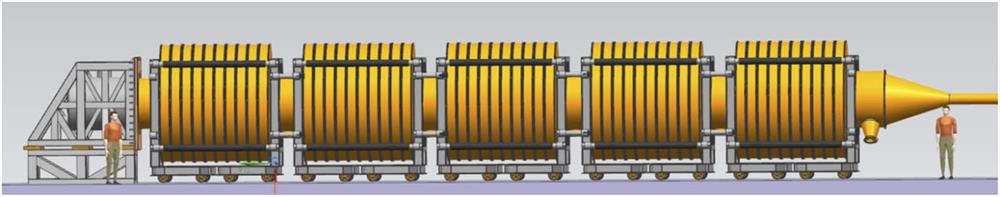
Fig. 1. Schematic of M-50 machine comprising 50 identical linear transformer driver (LTD) cavities connected in series. Each cavity can give an output pulse of 90 kV/1 MA on a matched resistive load. The voltage pulses generated by the cavities are summed along the output transmission line, which operates as a magnetically insulated transmission line (MITL). The nominal output of the M-50 machine is 4.5 MV/1.0 MA.
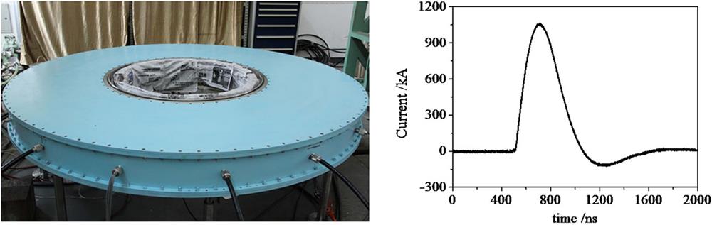
Fig. 2. Photograph of an LTD cavity (left), and typical output current waveform (right). The peak current obtained on a matched resistive load of 90 mΩ is ∼1.05 MA, and the corresponding charge voltage across the capacitors is ±90 kV. The rise time and full width at half maximum of the load current pulse are ∼124 and 312 ns, respectively.
Fig. 3. Schematic of M-50-1 machine. Ten LTD cavities are connected in series. I a1 and I a2 indicate the positions of the B-dot monitors that are used during the experiment to measure the anode current flowing along the output transmission line at 7 cm upstream from the first cavity and 68 cm downstream from the last cavity, respectively. I c2 indicates the location of the B-dot sensor for measuring the downstream cathode current. At each cross section, four B-dot probes are placed azimuthally to measure the current. U d indicates the position of a resistive divider located on the centerline of the load region for measuring the load voltage.
Fig. 4. Photograph of M-50-1 machine. The total length is ∼3.5 m, including ten LTD cavities and one extended section. Vacuum pumps are mounted at both ends of the machine. During the experiment, the vacuum pressure of the output transmission line section is normally below 5.0 × 10⁻³ Pa. A pre-magnetizing pulse supplied by discharging a 50-µ F capacitor into an 8-Ω water resistor in series is applied globally to all the cavities cores through the MITL cathode by using a movable contact under vacuum.
Fig. 5. Photograph of trigger unit, which comprises a mini-Marx, four 7.5-Ω/75-ns water-insulated pulse-forming lines, four laser-triggered gas switches, and 40 75-Ω output cables.
Fig. 6. Upstream anode current (red), downstream anode current (blue), downstream cathode current (green), and load voltage (black) at a charge voltage of ±85 kV with the radius r c of the straight MITL cathode being (a) 584, (b) 573, and (c) 563 mm.
Fig. 7. Characterization of electrode surfaces after discharge: r c = (a) 584, (b) 573, and (c) 563 mm.
|
Table 1. Peak values of voltage and current achieved in experiment. rc is the radius of the straight MITL cathode segment. Uc is the capacitor charge voltage. Ia1-pk and Ia2-pk are the maximum upstream and downstream anode currents, respectively. Ic2-pk and Ud-pk are the amplitudes of the cathode current and load voltage, respectively.


Set citation alerts for the article
Please enter your email address

© Copyright 2018-2021 | Chinese Laser Press. All Rights Reserved 沪ICP备15018463号-20