
Lin Chen, Wenkang Zou, Jihao Jiang, Liangji Zhou, Bing Wei, Fan Guo, An He, Weiping Xie, Jianjun Deng, Meng Wang, Jie Wang, Yuanjun Zhang. First results from a 760-GW linear transformer driver module for Z-pinch research[J]. Matter and Radiation at Extremes, 2021, 6(4): 045901
- Matter and Radiation at Extremes
- Vol. 6, Issue 4, 045901 (2021)
Abstract
I. INTRODUCTION
Petawatt-class pulsed power accelerators are required to drive Z-pinch implosions that can produce x-ray power as high as 1000 TW.1 They can be used for a wide variety of purposes, such as inertial confinement fusion, radiation physics, astrophysics, and other high-energy-density physics experiments.2,3
The linear transformer driver (LTD), which was first developed at the Institute of High Current Electronics in Tomsk, Russia, and the Centre d’études de Gramat in France, is a promising candidate as the primary power source for the next generation of pulsed power machines.4–7 The LTD has some attractive features compared to traditional technologies, one being that the energy transfer efficiency is supposedly high because pulses with fast rise time and high voltage can be achieved directly without a pulse compression section. Also, the components in an LTD-based facility have long lifetimes and high reliability because the charge transfer of each element is reduced greatly.
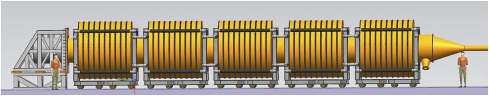
In the past decade, LTD technology has been investigated systematically around the world,8–24 and we have made a conceptual design of an LTD-based fusion-scale pulsed power accelerator.25 This fusion-scale machine comprises 3000 LTD cavities divided into 60 modules in parallel, and each module comprises 50 LTD cavities connected in series. The high-voltage pulses generated by each cavity are added along a magnetically insulated transmission line (MITL), and then the output currents of each module are summed at the convergent section where the Z-pinch load is located. A maximum current of ∼62 MA with a rise time (10%–90%) of ∼120 ns could be achieved on the load. Currently, a full-size module of the prospective fusion-scale pulsed power facility (known as M-50) is being developed in our laboratory. Figure 1 shows a schematic of the M-50 machine, which will serve as a test bed to assess the key technologies related to the fusion-scale machine. In particular, it is desirable to investigate the energy coupling efficiency of the output transmission line of the module because MITLs have been used successfully only in a few LTD-based machines, such as Ursa Minor at Sandia National Laboratories16 and the 1-MV LTD drivers in our laboratory19 and at CEA (Commissariat à l'énergie atomique et aux énergies alternatives).18 However, because (i) the currents flowing in the MITLs of those accelerators are much smaller than that of the M-50 machine and (ii) the rise times of the voltage pulses are also shorter than that of the M-50 machine, the operating conditions of the MITL should be quite distinct.
![]()
Figure 1.Schematic of M-50 machine comprising 50 identical linear transformer driver (LTD) cavities connected in series. Each cavity can give an output pulse of 90 kV/1 MA on a matched resistive load. The voltage pulses generated by the cavities are summed along the output transmission line, which operates as a magnetically insulated transmission line (MITL). The nominal output of the M-50 machine is 4.5 MV/1.0 MA.
To date, all the components of the M-50 machine have been fabricated completely and tested individually. In the past two years, we have investigated the overall performances of ten cavities connected in series, including the characterization of the power flow in the MITL, and the effectiveness of the multi-output trigger system and diagnostics. This pulsed power accelerator serves as a prototype of the M-50 machine to verify that the design of the latter meets the requirements. The experience gained from this work is also valuable for building the future accelerator. Hereinafter, this prototype is referred to as the M-50-1 machine.
In this paper, we present the results of tests on the M-50-1 machine with three different cathode radii for the output transmission line. The paper is organized as follows. The setup of the experiment and the configurations of the LTD cavity, the output transmission line, and the trigger system are described in Sec. II. The experimental results are presented in Sec. III, and a short discussion and summary are given in Sec. IV.
II. EXPERIMENTAL SETUP
Figure 2 shows a photograph of one of the LTD cavities, whose diameter and thickness are ∼2.9 and 0.27 m, respectively. A gaseous mixture of SF6 and N2 with a pressure of 0.1 MPa is used as the insulation medium in the cavity, in which 32 identical bricks are connected in parallel, each comprising two 100-nF/100-kV capacitors and one multi-gap gas switch.25 The equivalent inductance and resistance of one brick are ∼300 nH and 0.25 Ω, respectively. The insulation gas in the switches is dry air. All 32 switches are triggered by four trigger cables, each corresponding to eight switches. Magnetic cores are used to prevent current loss to the cavity shell. The volt-second product of the cores within a single cavity is greater than 28 mV s, which ensures that the core material undergoes no saturation during the discharge process. Each cavity of the M-50 machine has been tested individually.
![]()
Figure 2.Photograph of an LTD cavity (left), and typical output current waveform (right). The peak current obtained on a matched resistive load of 90 mΩ is ∼1.05 MA, and the corresponding charge voltage across the capacitors is ±90 kV. The rise time and full width at half maximum of the load current pulse are ∼124 and 312 ns, respectively.
We selected ten LTD cavities arbitrarily to assemble the M-50-1 machine, which is shown schematically in Fig. 3. The output transmission line comprises a straight electrode threading the ten LTD cavities, together with the inner conductors of the cavities. The inner electrode of the output transmission line is connected to the shell of the LTD cavity at the left end, and the inner straight electrode is connected to a conical conductor at the right end. A large-area diode (LAD) is used at the end of the conical segment. The inner electrode radius of the LTD cavity is 600 mm, which is also the size of the outer electrode of the output transmission line. Three straight inner electrodes of the output transmission line with radii of 584, 573, and 563 mm are tested individually. The corresponding vacuum impedances of the output transmission line are 1.62, 2.76, and 3.82 Ω. Because the nominal output of the M-50-1 machine is 0.9 MV/1.0 MA, the electrical stress on the inner conductor surface corresponding to the downstream cavities will exceed the explosive electron emission threshold (∼200 kV/cm). Therefore, during the experiment, the output transmission line of the M-50-1 machine operates as an MITL. According to the MITL flow model given by Creedon,26 the flow impedances of the output transmission line corresponding to the last LTD cavity are 0.91, 1.55, and 2.15 Ω, and the minimum magnetic insulation currents are 987, 579, and 419 kA when the nominal output is obtained from the M-50-1 machine.
![]()
Figure 3.Schematic of M-50-1 machine. Ten LTD cavities are connected in series.
In an ideal induction voltage adder, the inner electrode of the output transmission line has a stepped profile to ensure that the impedance of the output transmission line at each cavity section matches the summed equivalent impedance of the upstream cavities. Moreover, the timing of each successive cavity should be synchronized with the speed of electromagnetic wave propagation. However, one straight inner electrode was used in our experiment, this being because it is very difficult to manufacture a stepped inner electrode to match the corresponding impedance at each LTD section. Furthermore, according to particle-in-cell and circuit simulations, the impedance profile of the output transmission line has a negligible effect on the amplitude and rise time of the output pulse because the transmission time of the adder bore is only ∼8.1 ns for the M-50-1 machine, which is sufficiently less than the rise time of the output pulse.
The ten LTD cavities are mounted vertically on a supporting structure and connected one by one (Fig. 4) and then compressed inwardly from both sides by the supporting structure to ensure that they are electrically connected and vacuum sealed effectively. The total length of the LTD cavities is ∼2.7 m, and the length of the conical segment is 0.8 m. The anode of the MITL is made of stainless steel and has a fixed radius. The cathode of the MITL is made of aluminum alloy 7075 at the straight and conical sections; it reduces by ∼10 mm from the left end to the right end in the conical segment, which is terminated by an LAD. The A-K gap of the diode is ∼23 mm, and the front surface of its cathode electrode is covered with velvet cloth to facilitate electron emission.
![]()
Figure 4.Photograph of M-50-1 machine. The total length is ∼3.5 m, including ten LTD cavities and one extended section. Vacuum pumps are mounted at both ends of the machine. During the experiment, the vacuum pressure of the output transmission line section is normally below 5.0 × 10⁻³ Pa. A pre-magnetizing pulse supplied by discharging a 50-
There are 320 switches in the M-50-1 machine, triggered by 40 trigger cables. Figure 5 shows the trigger system used in the experiment. The mini-Marx comprises two 1-µF capacitors and a field distortion switch located in an oil tank. The field distortion switch is controlled by another commercial pulsed power generator. The storage energy in the mini-Marx transfers to the pulse-forming lines after the conduction of the field distortion switch. The pulse-forming lines are discharged by laser-triggered gas switches that are triggered externally by a YAG laser. The laser works at the fourth harmonic and outputs a 266-nm laser beam. The energy in the pulse-forming lines is compressed significantly by the laser-triggered gas switches, and a high-voltage pulse with a rise time of ∼20 ns and a peak value above 100 kV can be achieved on each cable when they are terminated with matched loads. Because the laser-triggered gas switches work well at a very low working coefficient, the pre-fire probability is very low, and the trigger system used is very reliable.
![]()
Figure 5.Photograph of trigger unit, which comprises a mini-Marx, four 7.5-Ω/75-ns water-insulated pulse-forming lines, four laser-triggered gas switches, and 40 75-Ω output cables.
III. EXPERIMENTAL RESULTS
In our experiments, the charge voltage of the capacitors was increased from ±35 to ±90 kV step by step. The initial experiments with low charge voltage were aimed at conditioning the gas switches and the MITL in the M-50-1 machine. The experimental results at a charge voltage of ±85 kV with different MITL cathode configurations are presented in Fig. 6. For each case, three successive shots were conducted at intervals of 20 min, and the results shown were obtained by averaging the measured current and voltage waveforms of each shot. The amplitudes of the currents and voltages are given in Table I. The difference between the anode and cathode currents near the last cavity represents the sheath current flowing in the MITL A-K gap, and the difference of the anode current between the upstream and downstream sections indicates that current loss exists in the MITL section.
![]()
Figure 6.Upstream anode current (red), downstream anode current (blue), downstream cathode current (green), and load voltage (black) at a charge voltage of ±85 kV with the radius
| rc (mm) | Uc (kV) | Ia1-pk (kA) | Ia2-pk (kA) | Ic2-pk (kA) | Ud-pk (kV) |
|---|---|---|---|---|---|
| 584 | ±85 | 960 | 744 | 628 | 596 |
| 573 | ±85 | 868 | 860 | 694 | 766 |
| 573 | ±90 | 912 | 912 | 721 | 832 |
| 563 | ±85 | 812 | 701 | 695 | 752 |
Table 1. Peak values of voltage and current achieved in experiment. rc is the radius of the straight MITL cathode segment. Uc is the capacitor charge voltage. Ia1-pk and Ia2-pk are the maximum upstream and downstream anode currents, respectively. Ic2-pk and Ud-pk are the amplitudes of the cathode current and load voltage, respectively.
Clearly, the anode and cathode current waveforms exhibit a much higher reversal than that of the 1-MV/100-kA LTD-based machine.19 It seems that the M-50-1 machine is terminated by an under-matched load. However, because the downstream B-dot sensors for anode current diagnostics are only ∼10 cm from the diode, the current obtained at this location could be regarded as the load current. The load impedances when the voltage reaches its maximum value are 0.8, 0.89, and 1.07 Ω in the three cases. The matched load impedance of the M-50-1 machine is 0.9 Ω, which is not significantly greater than those values. Therefore, the reversal of the current waveforms is not due to the impedance mismatch between the M-50-1 machine and the diode load. In fact, it is due mainly to gap closure by plasma in the A-K gap of the diode, which is related to the longer pulse rise time.
Some parts of the MITL anode and cathode surfaces after the experiments are shown in Fig. 7, where a few black spots can be seen on the electrodes surfaces. The largest black spots occurred in the first case behind the last cavity, which implies that a severe breakdown happened. In the third case, there were several small but evident black spots on the anode and cathode surfaces of the last cavity. The second case exhibited the best performance, with only some gray spots on the electrode surfaces of the last cavity. The upstream anode current (Ia1) reversal in Fig. 6(b) is also lower than that in the other two cases, and a higher load voltage was achieved.
![]()
Figure 7.Characterization of electrode surfaces after discharge:
The MITL configuration of the M-50 machine was designed using the same methodology as that for the Ursa Minor and Hermes III machines.27 As shown in Fig. 1, the 50 cavities of the M-50 machine are divided into five groups, each with ten cavities. Between adjacent groups, a 0.8-m-long connecting tube is used to accommodate the vacuum pumps, electrical diagnostics, and assembling operations. The inner conductor of the voltage adder section has nine segments. Five straight segments with different diameters are used in each cavity group, and a continuous taper geometry is used at each connecting tube section. The operation impedance of the MITL at the last cavity of each group is designed to match the summed impedance of the upstream drivers. According to these design criteria, the optimum radius of the MITL cathode conductor for the M-50-1 machine is 584 mm, whereas serious current loss and breakdown are observed with a 584-mm cathode conductor. This may be because the rise time of the output pulse in the M-50-1 machine is sufficiently greater than those in the Ursa Minor and Hermes III accelerators. Also, it takes much longer to establish the magnetic insulation than it does in the other two cases, resulting in higher current loss while establishing the insulation. The energy deposition in the MITL anode is so large that it may be enough to initialize plasma generation and ion emission from the anode, thereby enhancing the current loss. Furthermore, each induction cavity of the Hermes III machine is driven by four pulse-forming lines, and an azimuthal network is used to symmetrize the power flow in the MITL. The jitter of the conduction time of the switches in the LTD cavities will lead to asymmetric power flow in the output transmission line section, but an azimuthal transmission line cannot be used in the M-50-1 machine. The diameter of the MITL cathode conductor is much larger than that of Ursa Minor, thereby increasing greatly the time for the current flow to homogenize around the coax and possibly resulting in more energy loss in the M-50-1 machine than in Ursa Minor. Finally, the pulse width of the Hermes III machine is only ∼40 ns, and the MITL extension that is used provides the time isolation that makes the operation of the adder largely independent of the diode impedance conditions. However, because the pulse width of the M-50-1 machine exceeds 300 ns and the MITL extension behind the last cavity is only 0.8 m, it is impossible to prevent the discharge of the capacitors in the LTD cavities from being influenced by the LAD time history.
In the second case with a slightly small MITL cathode conductor diameter, the LAD impedance when the current reaches its maximum value is lower than the MITL flow impedance. The reflected wave generated at the load part propagates backward and reduces the width of the electron layer, which is very helpful for decreasing the current loss and energy deposition in the MITL. Therefore, the anode current transmission efficiency is very high, and the highest load voltage is obtained in this case.
It is also strange that the breakdown in the MITL gap in the third case is more severe than that in the second case, given that the gap distance increases. As is well known, the electron emission threshold is ∼200 kV/cm for aluminum. However, in the third case the maximum electric field is only ∼200 kV/cm according to the peak voltage in Fig. 6(c), and this critical value may result in nonuniform electron emission from the cathode.
Table I also gives the experimental results for the second case at a charge voltage of ±90 kV. The amplitudes of the anode currents at the upstream and downstream sections are both 912 kA, the peak values of the cathode current near the LAD and the load voltage are 721 kA and 832 kV, respectively, and the maximum power transferred to the load area is 0.76 TW. Note also that the amplitude of the experimental anode current is slightly lower than the nominal output of 1 MA, and the rise time is ∼130 ns, which is also longer than the nominal value of 120 ns. These discrepancies might be due to the additional inductance resulting from the nonuniform discharge of the LAD. We suppose that there are only a few discharge channels because only two or three arcing spots were evident on the velvet cloth after disassembling the diode and MITL cathode stalk. Nevertheless, this is the maximum power generated directly by a fast LTD with mega-ampere current output to date.
IV. SUMMARY
Herein, we have described the results of tests on a ten-stage LTD cavity system. The M-50-1 machine has been commissioned successfully, and the charging, triggering, pre-magnetization, vacuum, and data-monitoring systems function normally. The results show that the output of the M-50-1 machine is influenced strongly by the configuration of the MITL cathode conductor. Severe breakdown occurs when the MITL cathode radius is 584 mm, even though the flow impedance of this MITL matches the driver impedance. When the MILT cathode radius is 573 mm, an 832-kV/912-kA pulse with a rise time of 130 ns is delivered into the e-beam diode, and the maximum power obtained is 0.76 TW. The MITL system does not perform as expected, and some issues remain to be resolved. The stated factors that differ from the power flow conditions in the Hermes III accelerator should be considered carefully, and we will continue to explore these problems.
ACKNOWLEDGMENTS
Acknowledgment. We are grateful for the financial support from the National Natural Science Foundation of China (Grant No. 51907181). We also thank Yingmin Dai for the mechanical design, Yu Ding and Junjun Kang for maintaining the laser system, and Ke Wang for proofreading the manuscript of this paper.
References
[1] M. E.Cuneo, H. C.Ives, M. G.Mazarakis, W. A.Stygar, R. A.Vesey et al. Theoretical z-pinch scaling relations for thermonuclear-fusion experiments. Phys. Rev. E, 72, 026404(2005).
[2] M. S.Derzon, M. K.Matzen, D. D.Ryutov. The physics of fast Z pinches. Rev. Mod. Phys., 72, 167(2000).
[3] R.Paul Drake. High Energy Density Physics-Fundamentals, Inertial Fusion, and Experimental Astrophysics(2006).
[4] A. N.Bastrikov, V. G.Durakov, A. A.Kim, B. M.Kovalchuk, S. N.Volkov et al. 100 ns current rise time LTD cavity, 1491(2001).
[5] G.Auriel, M.Caron, T.d’ Almeida, R.Maisonny, J. M.Plewa, M.Ribière, M.Toury. Investigating the performances of a 1 MV high pulsed power linear transformer driver: From beam dynamics to x radiation. Phys. Rev. Accel. Beams, 19, 120401(2016).
[6] W. E.Fowler, M. G.Mazarakis, D.McDaniel, C. L.Olson, S. T.Rogowski et al. Operation and performance of the first high current LTD at Sandia National Laboratories, 155(2005).
[7] W. E.Fowler, F. W.Long, M. G.Mazarakis, D. H.McDaniel, C. L.Olson et al. High current fast 100 ns LTD driver development in Sandia laboratory, 390(2005).
[8] A. N.Bastrikov, A. A.Kim, B. M.Kovalchuk et al. 1 MV ultra-fast LTD generator, 853(2003).
[9] L.Chen, J. J.Deng, L. J.Zhou et al. Design and experiment of linear transformer driver stage. High Power Laser Part. Beams, 18, 1749(2006).
[10] D. L.Johnson, J. J.Leckbee, J. E.Maenchen et al. Design, simulation, and fault analysis of a 6.5-MV LTD for flash X-ray radiography. IEEE Trans. Plasma Sci., 34, 1888(2006).
[11] A. N.Bastrikov, A. A.Kim, V.Sinebryukhov et al. Design and first tests of five 100 GW fast LTD cavities driving an e-beam diode load, 144(2007).
[12] T. X.Liang, A. C.Qiu, F. J.Sun et al. Simulation and primary experimentation of linear transformer driver module. High Voltage Eng., 33, 18(2007).
[13] V. M.Alexeenko, A. N.Bastrikov, F.Bayol, V. G.Durakov, W. E.Fowler, S. V.Frolov, R. M.Gilgenbach, A. A.Kim, B. M.Kovalchuk, K.LeChien, M. G.Mazarakis, D. H.McDaniel, C.Olson, J.Porter, V. A.Sinebryukhov, K. W.Struve, W. A.Stygar, V. A.Visir, S. N.Volkov. Development and tests of fast 1-MA linear transformer driver stages. Phys. Rev. Spec. Top.–Accel. Beams, 12, 050402(2009).
[14] L.Chen, Y.Li, J.Ren, L. J.Zhou, W. K.Zou et al. The design and the first test results of a fast LTD stage. Acta Phys. Pol. A, 115(2009).
[15] W. E.Fowler, K. L.LeChien, M. G.Mazarakis et al. High-current linear transformer driver development at Sandia National Laboratories. IEEE Trans. Plasma Sci., 38, 704(2010).
[16] B.Bui, M.Caron, S. R.Cordova, J. J.Leckbee, B. V.Oliver, T.Romero, R.Rosol, M.Toury, T. J.Webb, D.Ziska. Linear transformer driver (LTD) research for radiographic applications, 614(2011).
[17] W. E.Fowler, B. S.Stoltzfus, J. R.Woodworth et al. Compact 810 kA linear transformer driver cavity. Phys. Rev. Spec. Top.–Accel. Beams, 14, 040401(2011).
[18] F.Bayol, M.Caron, F.Cubaynes, R.Delplanque, P.Genez, A. A.Kim, C.Legras, M.Mouillet, M.Parzych, M.Toury. Development of a 1 MV ultra-fast LTD generator, 619(2011).
[19] L.Chen, M.Wang, W. P.Xie, L. J.Zhou, W. K.Zou et al. 100 GW fast linear transformer driver generator. High Power Laser Part. Beams, 24, 651(2012).
[20] L.Chen, D. G.Liu, L. Q.Liu, L.Zhang, W. K.Zou et al. Investigation on high inductive helical supported magnetically insulated transmission line on a 10-stage linear transformer driver system. Phys. Rev. Spec. Top.–Accel. Beams, 15, 110401(2012).
[21] F.Cartier, P.Combes, M.Toury et al. Transfer and test of a 1 MV LTD generator at CEA, 766(2013).
[22] L.Chen, Y. M.Dai, M.Wang, W. P.Xie, W. K.Zou et al. Design of the linear transformer driver stage prototype for Z-pinch driver. High Power Laser Part. Beams, 26, 095007(2014).
[23] G.Brent, E. M.Campbell, D. H.Froula, D. B.Reisman, R. B.Spielman et al. Conceptual design of a 15-TW pulsed-power accelerator for high-energy-density-physics experiments. Matter Radiat. Extremes, 2, 204(2017).
[24] F.Guo, J. H.Jiang, L. Q.Liu, B.Wei, W. K.Zou et al. Coaxial–conical transition in magnetically insulated transmission lines. IEEE Trans. Plasma Sci., 46, 1913(2018).
[25] L.Chen, Y.Liu, M.Wang, L. J.Zhou, W. K.Zou et al. Development of a fusion-oriented pulsed power module. Phys. Rev. Accel. Beams, 22, 030401(2019).
[26] J. M.Creedon. Relativistic Brillouin flow in the high υ/γ diode. J. Appl. Phys., 46, 2946(1975).
[27] J. A.Alexander, J. P.Corley, G. J.Denison, K.Hodge, D. L.Johnson et al. Performance of the Hermes-III pulse forming lines, 575(1989).


Set citation alerts for the article
Please enter your email address

© Copyright 2018-2021 | Chinese Laser Press. All Rights Reserved 沪ICP备15018463号-20