
Chuan Qiu, Niannian Chen, Ling Wu, Yong Fan, Guanghai Liu. Six-Step Hybrid Phase Shift Technique in Digital Photoelasticity[J]. Acta Optica Sinica, 2023, 43(10): 1026001
- Acta Optica Sinica
- Vol. 43, Issue 10, 1026001 (2023)
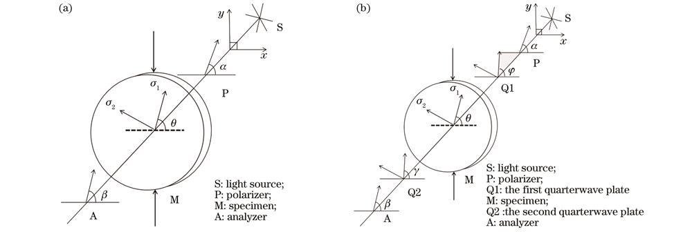
Fig. 1. Polarization optical system. (a) Planar polarization optical system; (b) circular polarization optical system

Fig. 2. Isoclinic images. (a) Six-step phase shift with monochromatic light; (b) ten-step phase shift with monochromatic light; (c) ten-step phase shift with white light
Fig. 3. Digital photoelastic image acquisition system
Fig. 4. Wrapped isoclinic images. (a)(d)(g) F=200 N, D=50 mm; (b)(e)(h) F=350 N, D=50 mm; (c)(f)(i) F=200 N, D=40 mm
Fig. 5. Unwrapped isoclinic images. (a) Ten-step phase shift; (b) proposed method
Fig. 6. Isochromatic images. (a) Ten-step phase shift; (b) proposed method
Fig. 7. Plot of isochromatic difference. (a) Location 1 of disc; (b) location 2 of disc
Fig. 8. Wrapped isochromatic images. (a)(d) F=300 N, D=50 mm; (b)(e) F=350 N, D=50 mm; (c)(f) F=200 N, D=40 mm
|
Table 1. Intensity equations of six-step phase shift
|
Table 2. Intensity equations of four-step phase shift technique
| |||||||||||||||||
Table 3. Three images of planar polarized light field
| |||||||||||||||||||||||||||||||
Table 4. Three images of circularly polarized optical field
| ||||||||||||||||||||||||
Table 5. Average deviation results of isoclinic and isochromatic before and after noise of each method
| ||||||||||||||||||||
Table 6. Deviation results of isoclinic caused by azimuth of polarizer and analyzer
| ||||||||||||||||||||
Table 7. Deviation results of isochromatic caused by the azimuth of the second quarter wave and the analysis mirror
|
Table 8. Average deviation results of the isoclinic and isochromatic

Set citation alerts for the article
Please enter your email address
© Copyright 2018-2021 | Chinese Laser Press. All Rights Reserved 沪ICP备15018463号-20