
Xiaorong Zhang, He Yang, Xiaohong Sun. Study on Focusing Characteristics of Double-Period Graded Photonic Crystal Lens Based on Biconical Interferometry[J]. Laser & Optoelectronics Progress, 2022, 59(17): 1709001
- Laser & Optoelectronics Progress
- Vol. 59, Issue 17, 1709001 (2022)
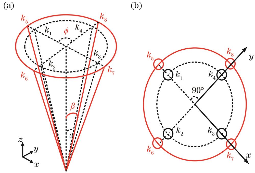
Fig. 1. Double-cone interference model. (a) Main view; (b) top view
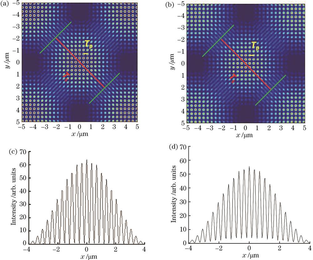
Fig. 2. Interference patterns and GPC intensity distribution at θ=45° and β=50°. (a) Interference pattern when the angle between the polarization direction of each beam and the x-axis is the same; (b) interference pattern when the angle between the polarization direction of each beam and the x-axis is different; (c) GPC intensity distribution when the polarization direction of each beam is the same and y=0; (d) GPC intensity distribution when the polarization direction of each beam is different and y=0
Fig. 3. Design of GPC lens when θ=45° and β=50°. (a) GPC intensity distribution when y=0; (b) GPC lens structure when the light intensity threshold is 12.5
Fig. 4. Transmission spectrum of GPC lens under TM polarization when θ=45° and β=50°
Fig. 5. GPC structures along the x-axis from the positive center of the lens structure toward the edge in the three cases when the sine difference of the inner and outer cone is fixed. (a) Intensity distribution; (b) radius distribution of lens media column
Fig. 6. Effective refractive index of the GPC lens along the x-axis for the three cases when the sine difference of the inner and outer cone is fixed
Fig. 7. Intensity distributions of the three lenses in the x-z plane when the sine difference of the inner and outer cone is fixed. (a) θ=30° and β=33.98°; (b) θ=45° and β=50°; (c) θ=60° and β=67.66°
Fig. 8. Focusing characteristics of the three lenses when the sine difference of the inner and outer cone is fixed. (a) Intensity distribution along z-axis; (b) intensity distribution along x-axis focal plane
Fig. 9. GPC structures along the x-axis from the positive center of the lens structure toward the edge for the three cases when the outer cone β is fixed .(a) Intensity distribution; (b) radius distribution of lens media column
Fig. 10. Effective refractive index of the three GPC lenses along the x-axis when the outer cone β is fixed
Fig. 11. Intensity distribution of the three GPC lenses in the x-z plane when the outer cone angle β is fixed. (a) θ=60° and β=67.66°;(b) θ=58°and β=67.66°; (c) θ=56° and β=67.66°
Fig. 12. Focusing characteristics of the three GPC lenses when the outer cone angle β is fixed. (a) Intensity distribution along z-axis; (b) intensity distribution along x-axis focal plane
Fig. 13. Effect of polarization angle on structure when β=67.66° and θ=56°. (a) Effect of polarization angle on the radius distribution of the dielectric column from the center to the edge along the x-axis; (b) effect of polarization angle on the effective refractive index along the x-axis
Fig. 14. Intensity distribution of the GPC lenses in the x-z plane. (a) Intensity distribution of different polarization directions; (b) intensity distribution when all the polarization directions are 0°
Fig. 15. Effect of polarization angle on the focusing characteristics of the GPC lens. (a) Intensity distribution along z-axis; (b) intensity distribution along x-axis focal plane

Set citation alerts for the article
Please enter your email address
© Copyright 2018-2021 | Chinese Laser Press. All Rights Reserved 沪ICP备15018463号-20