
Shuo Jiang, Linghui Yang, Yongjie Ren, Jigui Zhu. Defect Detection in Mirror-Like Object Surface Based on Phase Deflection[J]. Laser & Optoelectronics Progress, 2020, 57(3): 031201
- Laser & Optoelectronics Progress
- Vol. 57, Issue 3, 031201 (2020)
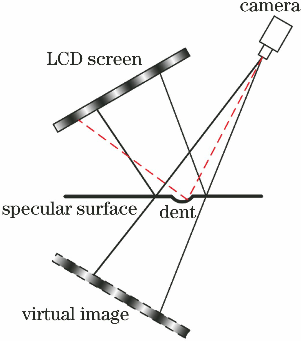
Fig. 1. Schematic of mirror surface defect detection based on PMD
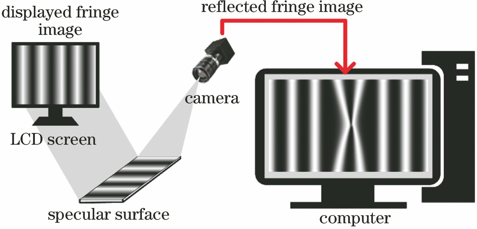
Fig. 2. Mirror surface defect detection system based on PMD
Fig. 3. Extraction of wrapped phase Φ(x,y). (a) Sequence image of four-step phase-shift; (b) wrapped phase Φ(x,y)
Fig. 4. Wrapped phase jump error. (a) Wrapped phase Φ(x,y) and corresponding a of jump error in some row; (b) local amplification of wrapped phase jump error
Fig. 5. Correction of wrapped phase jump error. (a) Wrapped phase with and without correction; (b) local amplification of wrapped phase correction effect
Fig. 6. Calculation of period index k(x,y). (a) Sequence image of Gray-code; (b) period index k(x,y)
Fig. 7. Unfolding of wrapped phase. (a) Wrapped phase Φ(x,y); (b) period index k(x,y) of wrapped phase; (c) absolute phase ?(x,y)
Fig. 8. Error in phase unwrapping. (a) Diagram of absolute phase intensity; (b) absolute phase of marked line in Fig. 8 (a)
Fig. 9. Correction of period index k(x,y)
Fig. 10. Painted fuselage sample
Fig. 11. Diagram of experimental system
Fig. 12. Defect detection results without and with period index correction. (a)(b) Intensity images of absolute phase; absolute phases of marked line in (c) Fig. 12 (a) and (d) Fig. 12 (b); defect detection results in (e) Fig. 12 (a) and (f) Fig. 12 (b)
Fig. 13. Defect locations and contours. (a) Defect locations and contours on wrapped phase image; (b) local amplification of defects
Fig. 14. Defect locations and contours on painted surface. (a) Hairy fiber; (b) sagging; (c) paint slag;(d) scratch before paint; (e) dirt; (f) dent; (g) craters; (h) bump


Set citation alerts for the article
Please enter your email address

© Copyright 2018-2021 | Chinese Laser Press. All Rights Reserved 沪ICP备15018463号-20