
Zeyu Zhang, Yao Fan, Qin Xu, Yuzhou Chen, Jiasong Sun, Qian Chen, Chao Zuo. Review of computational optical microscopy imaging technology based on smartphone platform[J]. Infrared and Laser Engineering, 2022, 51(2): 20220095
- Infrared and Laser Engineering
- Vol. 51, Issue 2, 20220095 (2022)
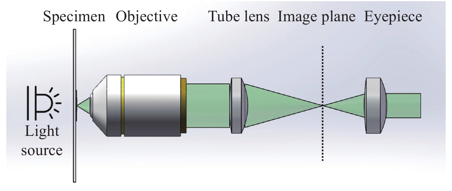
Fig. 1. Infinite microscope optical system

Fig. 2. Type of objective lens in microscope system based on smartphone platform. (a) Standard microscopic imaging light path; (b) Customized single lens; (c) Self-correcting microscopic optical path of inverted camera lens of smartphone
Fig. 3. Schematic diagram of various microscopic imaging systems of smartphone platform based on standard microscopic imaging optical path. (a) Schematic diagram of microscope based on mobile phone platform proposed by Breslauer et al[40]; (b) Schematic diagram of microscope based on smartphone platform proposed by Shan et al[57]; (c) Schematic diagram of microscope based on smartphone platform proposed by Shrivastava et al[58]
Fig. 4. Schematic diagram of microscopic imaging systems of various smartphone platforms based on spherical lens. (a) Schematic diagram of microscope based on smartphone platform proposed by bogoch et al[62]; (b) Schematic diagram of microscope based on smartphone platform proposed by Jahan Tigh et al[42]; (c) Schematic diagram of microscope based on smartphone platform proposed by kutay et al[65]; (d) Schematic diagram of microscope based on smartphone platform proposed by Zeng et al[63]; (e) Schematic diagram of microscope based on smartphone platform proposed by Agbana et al[64]
Fig. 5. Schematic diagram of various micro imaging systems of smart phone platform based on aspheric lens. (a) Schematic diagram of microscope based on smart phone platform proposed by ARPA et al[66]; (b) Schematic diagram of microscope based on smartphone platform proposed by Felton et al[67]
Fig. 6. Schematic diagram of microscopic imaging systems of various smartphone platforms based on PDMS lens. (a) Schematic diagram of the manufacturing process of PDMS inkjet printing lens and its microscope based on smartphone platform proposed by Sung et al[73]; (b) Schematic diagram of microscope based on smartphone platform proposed by Sung et al[74]; (c) Schematic diagram of fabrication process of liquid-driven lens and microscope based on smartphone platform proposed by Fuh et al[75]
Fig. 7. Comparison of microscope structures based on smartphone platforms[76]. (a) Schematic diagram of a spherical lens-based cell phone microscope; (b) Schematic of a cell phone microscope based on a standard infinity microscope system; (c) Schematic diagram of a microscope based on an inverted mobile phone lens
Fig. 8. Schematic diagram of various self-correcting intelligent mobile phone platform microscopic imaging systems based on inverted mobile phone lenses. (a) Schematic diagram of the smartphone platform-based microscope proposed by Switz et al[76]; (b) Schematic diagram of the smartphone platform-based microscope proposed by D’Ambrosio et al[77]; (c) Schematic diagram of the smartphone platform-based microscope proposed by Kim et al[78]; (d) Schematic diagram of the microscope based on smartphone platform by Kheireddine et al[79]
Fig. 9. Evolution of mobile image sensor
Fig. 10. Schematic diagram of typical computational optics high-throughput microscopy imaging technology based on advanced sensors and its principle[86]
Fig. 11. Schematic diagram of the computational optics high-throughput microscope based on the mobile phone platform. (a) Schematic diagram of the microscope based on the smartphone platform proposed by Tseng et al.[87]; (b) Schematic diagram of the microscope based on the smartphone platform proposed by Seung et al[88]
Fig. 12. Schematic diagram of various microscope applications based on smartphone platforms. (a) Overall work flow chart of "blood analysis" application proposed by Zhu et al[93]; (b) Work flow chart of Android application customized and developed by Navruz et al[94]; (c) Schematic diagram of mobile phone fluorescence microscope and application proposed by Wei et al[95]; (d) Workflow diagram of Android application proposed by Phillips et al[96]
Fig. 13. Steps for quantitative, reproducible imaging using a smartphone platform-based microscope[97]. (a) Standardize illumination source and brightness; (b) Set focal state on a field with known dimensions or features; (c) Set exposure and gain using a clear field of view; (d) Acquire images of samples while keeping capture settings constant; (e) Information content can be preserved by selecting lossless or high quality compression settings
Fig. 14. (a) Work flow chart of wireless transmission using smart phone platform proposed by Zimic[101]; (b) Workflow diagram of micro system based on smart phone platform proposed by Rabha et al[110]; (c) Work flow chart of real-time wireless observation of microscope system based on smart phone platform proposed by Wan et al[103]
Fig. 15. Various smartphone platform-based microscopes combined with deep learning. (a) Schematic diagram of smartphone microscope system structure and deep learning results proposed by Rivenson et al[117]; (b) The structure diagram of smartphone microscope system and the workflow diagram of two deep learning networks proposed by Han et al [118]; (c) The structure diagram of smartphone microscope system and the workflow diagram based on deep learning style transfer method proposed by Bian et al[119]
Fig. 16. Schematic diagrams of various brightfield microscopes based on smartphone platforms. (a) Schematic diagram of the brightfield microscope based on the smartphone platform proposed by Hutchison et al[128]; (b) Schematic diagram of the smartphone platform-based brightfield microscope proposed by Orth et al[129]; (c) Schematic diagram of brightfield microscope based on smartphone platform proposed by Cai et al[130]
Fig. 17. Schematic diagram of various darkfield microscopes based on smartphone platforms. (a) Schematic diagram of the microscope based on the smartphone platform proposed by Sun et al[134]; (b) Schematic diagram of the smartphone platform-based microscope proposed by Ogasawara et al[135]; (c) Schematic diagram of the smartphone platform-based microscope proposed by Kheireddine et al[131]; (d) Schematic diagram of the microscope based on the smartphone platform proposed by Rabha et al[110]
Fig. 18. Schematic diagram of various differential phase contrast microscopes based on smartphone platforms. (a) Schematic diagram of the smartphone platform-based microscope proposed by Jung et al[136]; (b) Schematic diagram of the smartphone platform-based microscope proposed by Ogasawara et al[135]; (c) Schematic diagram of the smartphone-based microscope proposed by Kheireddine et al[131]
Fig. 19. Schematic diagram of various quantitative phase imaging microscopes based on smartphone platforms. (a) Schematic diagram of the smartphone platform-based microscope proposed by Lee et al[88];(b) Schematic diagram of the microscope based on the smartphone platform proposed by Meng et al[153]; (c) Schematic diagram of the smartphone platform-based microscope proposed by Phillips et al[96]
Fig. 20. Schematic diagrams of various smartphone-based fluorescence microscopes. (a) Schematic diagram of the microscope based on the smartphone platform proposed by Coskun et al; (b) Schematic diagram of the microscope based on the smartphone platform proposed by Cai et al[130]; (c) Schematic diagram of the microscope based on the smartphone platform proposed by Zhu et al[162]; (d) Schematic diagram of the microscope based on the smartphone platform proposed by Wei et al[95]; (e) Schematic diagram of the microscope based on the smartphone platform proposed by Dai et al[165]
Fig. 21. Schematic diagram of the polarization microscope system based on the smartphone platform proposed by Pirnstill et al; (b) No polarizer images of starch molecules were collected; (c) The polarizer and polarizer cross collect the images of starch molecules at 90°[170]
|
Table 1. Advantages and disadvantages of three types of new microscopic imaging optical path designs based on smartphone platforms

Set citation alerts for the article
Please enter your email address
© Copyright 2018-2021 | Chinese Laser Press. All Rights Reserved 沪ICP备15018463号-20