
Song Ye, Haofang Yan, Xiaobing Sun, Jiejun Wang, Xinqiang Wang, Fangyuan Wang, Shu Li, Yongying Gan, Wentao Zhang. Modified Image Demodulation Algorithm for Spatially Modulated Full-Polarization Imaging Systems[J]. Acta Optica Sinica, 2019, 39(6): 0607001
- Acta Optica Sinica
- Vol. 39, Issue 6, 0607001 (2019)
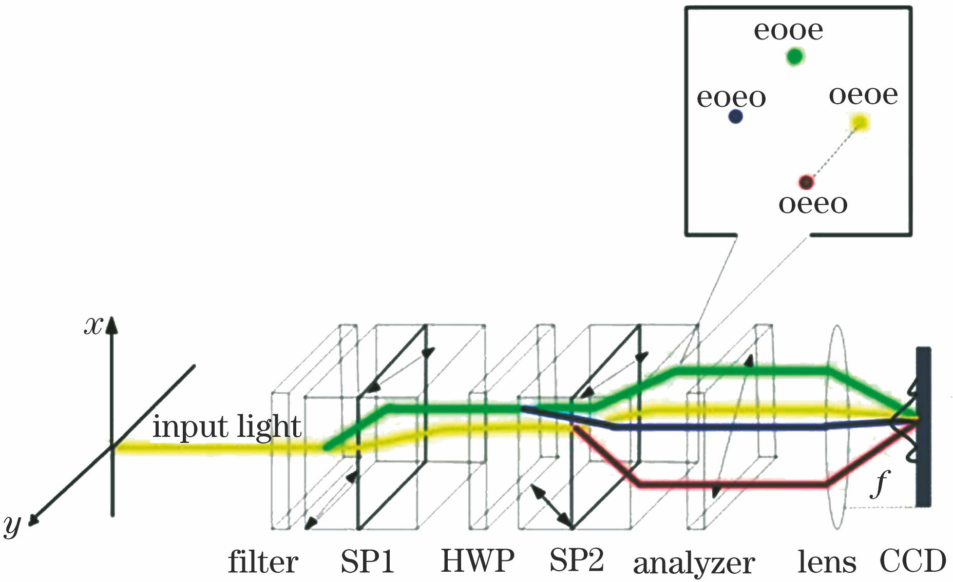
Fig. 1. Optical principle of spatially modulated full-polarization imaging system
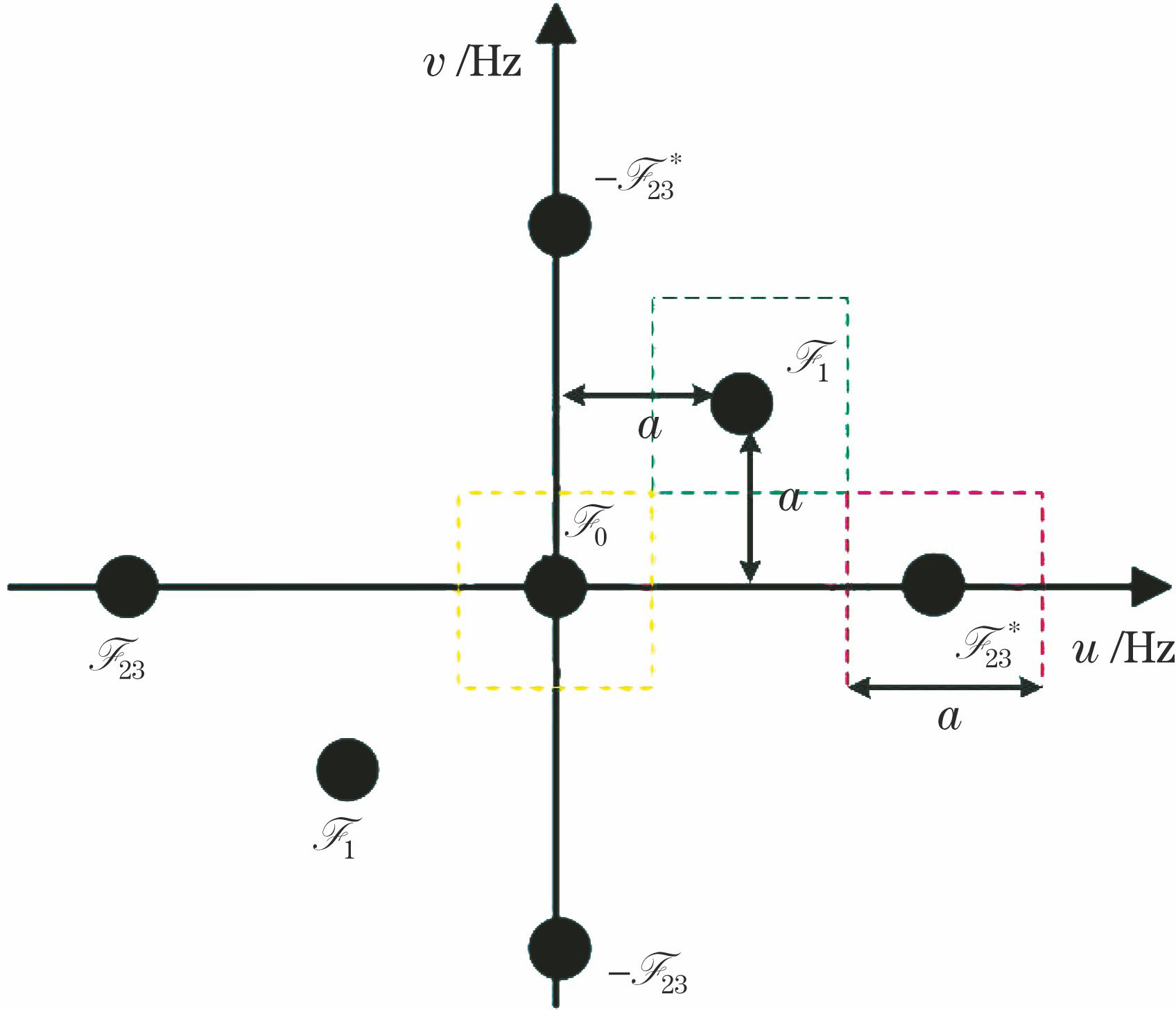
Fig. 2. Modulated image frequency spectrum diagram
Fig. 3. Original input polarization
Fig. 4. Reconstruction images. (a)-(d) Traditional demodulation algorithm; (e)-(h) modified demodulation algorithm
Fig. 5. Spectral response curve of CCD
Fig. 6. Interferograms. (a) [1,1,0,0]T; (b) [1,0,0,0]T
Fig. 7. Reconstruction images obtained by different algorithms for input polarization state [1,1,0,0]T. (a)-(e) Traditional demodulation algorithm; (f)-(j) modified demodulation algorithm
Fig. 8. Reconstruction images obtained by different algorithms for input polarization state [1,0,0,0]T. (a)-(e) Traditional demodulation algorithm; (f)-(j) modified demodulation algorithm
|
Table 1. System parameters
|
Table 2. PSNR between test image and traditional demodulation algorithm or modified demodulation algorithm
| |||||||||||
Table 3. DOP of images reconstructed by different algorithms

Set citation alerts for the article
Please enter your email address
© Copyright 2018-2021 | Chinese Laser Press. All Rights Reserved 沪ICP备15018463号-20