
Xueqi Chen, Aimin Jiang. Source Simulation Experimental System Based on Digital Micromirror Device[J]. Acta Optica Sinica, 2019, 39(10): 1011003
- Acta Optica Sinica
- Vol. 39, Issue 10, 1011003 (2019)
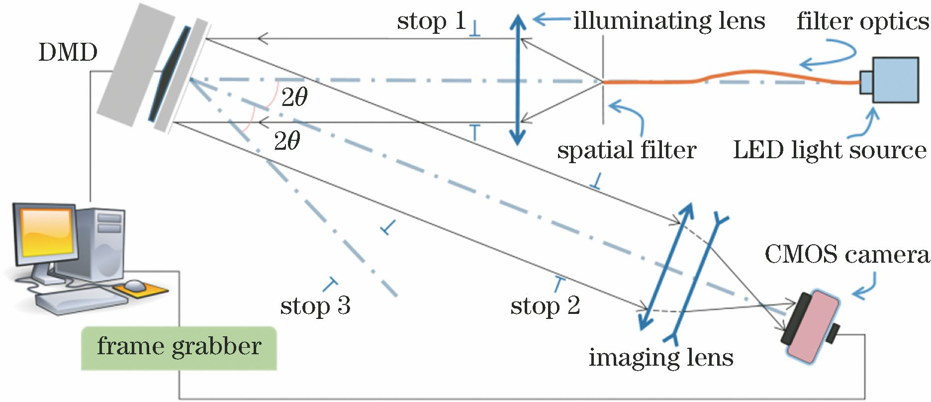
Fig. 1. Structural diagram of source simulation system based DMD
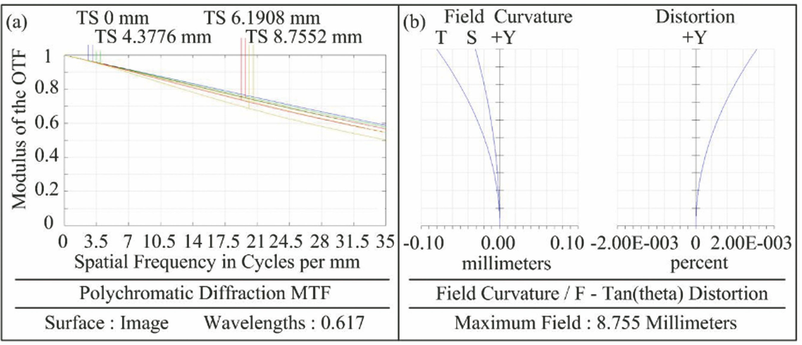
Fig. 2. Imaging performance of experimental system. (a) MTF curve; (b) field curvature and distortion
Fig. 3. DMD's azimuth in the imaging light path. (a) DMD array plane perpendicular to the lighting optical axis; (b) DMD array plane perpendicular to the imaging optical axis; (c) diagram of distance between Bi and Bj
Fig. 4. DMD mounted on optical platform with rotation angle of 45°
Fig. 5. Shaded model diagram of simulation system with Zemax non-sequence mode
Fig. 6. Distortion measurement template
Fig. 7. Distortion curves with different lighting sources. (a) Parallel source lighting; (b) ideal parallel source lighting; (c) non-parallel light source lighting (after point light source moving -1 mm along the axis); (d) non-parallel light source lighting (after point light source moving +1 mm along the axis)
Fig. 8. DMD pitch angle deviation, azimuth angle deviation, and roll angle deviation as functions of distortion in different FOVs
Fig. 9. Source simulation experimental system based on DMD. (a) Experimental light path; (b) collected image in distortion measurement experiment
Fig. 10. Distortion curve of experimental system
Fig. 11. Black and white grid images used to test contrast. (a) Input image of DMD; (b) acquired image of CMOS
|
Table 1. Main optical parameters of experimental system
|
Table 2. Table of feature points corresponding to three FOVs
| |||||||||||||||||||
Table 3. Distortion of system design, system simulation, and experiment


Set citation alerts for the article
Please enter your email address

© Copyright 2018-2021 | Chinese Laser Press. All Rights Reserved 沪ICP备15018463号-20