
Yuan Zhao, Haiyang Lu, Cangtao Zhou, Jungao Zhu. Overcritical electron acceleration and betatron radiation in the bubble-like structure formed by re-injected electrons in a tailored transverse plasma[J]. Matter and Radiation at Extremes, 2023, 8(1): 014403
- Matter and Radiation at Extremes
- Vol. 8, Issue 1, 014403 (2023)
Abstract
I. INTRODUCTION
The laser-plasma accelerator (LPA) has shown extraordinary potential in the compact particle acceleration field since it was first put forward in 1979.1–3 In the past few decades, a great deal of work on electron acceleration mechanisms has resulted in inspiring progress from the perspectives of theory, simulation, and experiment.4,5 In principle, high-charge electrons can be accelerated in a laser field directly (direct laser acceleration, DLA) and by a laser wake field (laser wake-field acceleration, LWFA).2 DLA, which occurs in an ion channel formed by the self-channeling effect, was first described by Pukhov et al.6 It has been validated that this approach can produce an overcritical electron beam because it can be applied to near-critical-density (NCD) plasmas or even at the surface of solid-density plasmas.7–9 However, it is challenging to maintain the electron beam quality owing to the tremendous impact of the laser field.10 Unlike in DLA, electrons are accelerated longitudinally and confined transversely in LWFA. In addition, the accelerating gradient of the wake field is independent of the radial position, while the transverse confinement force increases with radius. These two features are capable of conserving electron beam qualities such as the energy spread, emittance, and divergence.11 Meanwhile, the population of the witness bunch is restricted by the low fraction of electron self-trapping.2,12 Various schemes have been proposed to resolve the population limitation of self-injection, including ionization injection in high-Z gas,13,14 density transitions,15 irradiation of the wake field with another laser beam propagating in the vertical direction,16 and bow-wave injection.17 The electron charge is significantly enhanced from tens to hundreds of pC.18 When increasing the power of the incident laser to hundreds of TW or even to the PW scale, the maximal charge can reach up to several nC.19–21 Despite this, the LWFA total charge performance, particularly for high-energy electrons, is still not comparable to those of conventional radio-frequency sources.
The tailored plasma offers the possibility of improving beam quality through its remarkable contribution to LPA.22–24 The mechanism behind the tailored plasma is the rapid changing of the wavelength of the plasma wave through introduction of a density transition, as the electron plasma frequency is proportional to the electron density, i.e., ωpe ∝ ne. Bulanov et al. first studied the excitation of a plasma wave in an inhomogeneous plasma in 1998.25 In their regime, the phase velocity of the plasma decreased with a moderate decline of the plasma density in the laser propagating path. When the plasma phase velocity dropped to the quiver velocity of the background electrons, the Langmuir wave was broken. As a result, the electrons were trapped in the acceleration phase. The condition was totally different when the longitudinal density ramp was sharpened, i.e., kpLs < 1. Suk et al. showed that enormous numbers of electrons that were initially at the tail of a high-density wake field could enter the accelerating phase of the wake field as the plasma wavelength rose with a rapid density reduction.26 Numerous efforts to optimize the gradient, scale length, and density profile have been invested to obtain high-charge electron beams in LWFA.27–29 Unlike in a longitudinal density transition, a transverse density gradient is employed in LWFA to tilt the propagation axis of the laser pulse and induce wake-field asymmetry. As a result, it can considerably boost betatron oscillation and increase both the yield and energy of the produced photons.30,31 In order to increase the amount of charge in an accelerated electron bunch, further design improvements of the plasma density profile are still required.
In this paper, we propose a new scheme that utilizes a bubble-like structure formed by electron reflux to accelerate a high-charge electron beam. This is achieved via tailoring the plasma density transversely, which results in a curvature of the plasma wavefronts and thus controls the electron re-injection along the maximal plasma density. The electrons inside the bubble shape feel a strong longitudinal field that acts as the acceleration field and a varying transverse field that confines the electron oscillation in the vertical direction. Simulation results show that an over-critical-density electron beam is injected into the bubble and efficiently gains an energy of 500 MeV. Furthermore, the frequency of betatron oscillation ωβ is adjusted by the laser beam to ten times that in LWFA. This significantly raises the cut-off energy of the emitted photons to the range of MeV.
II. ELECTRON REFLUX
In a uniform plasma medium, the group velocity of a relativistic laser beam (a0 ≫ 1) is estimated to be
![]()
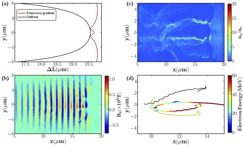
Figure 1.(a) The phase differences of the plasma wave after 20
| (0.5 mm) parameters | Values |
|---|---|
| Lasers | |
| Laser intensity I0 | 5 × 10²¹ W cm−2 |
| Laser wavelength λ0 | 1 μm |
| Laser period T0 | 3.33 fs |
| Waist radius of laser beam σ | 6 µm |
| Full duration at half maximum | 39.2 fs |
| Target | |
| Material | Aluminum |
| Electron density ne0 | 2nc |
| Plasma length L0 | 35 µm |
| Initial electron temperature Te | 10 eV |
Table 1. Simulation parameters.
We simulate the laser irradiating the transversely tailored plasma with the particle-in-cell (PIC) code EPOCH2D. To facilitate comparisons, the simulation parameters are kept the same as those used in the aforementioned theoretical calculation, as listed in Table I. The sampled window is X × Y = 40 × 30 µm2 with cell numbers of Nx × Ny = 2000 × 1500. A Gaussian laser beam is incident from the left boundary of the simulation box. According to the expression for the group velocity in the previous paragraph, the impact of the laser wavelength is on the term ω, which is independent of the density profile. Therefore, the curvature at the plasma front can be observed under various laser wavelength conditions. The laser wavelength used in the simulations is 1 µm, corresponding to a critical plasma density of nc = 1.1 × 1027 m−3.34 The plasma slab is located in the domain of 5 ≤ x ≤ 40 μm. We employ the same plasma density profile discussed in the last paragraph. The characteristic term ne0 = 2nc. It is worth noting that such a typical density distribution could be obtained by ablating a channel built of an array of nanotubes in an experiment.35 In fact, such a density profile has already been fabricated with hydrogen gas in a laboratory with the hydrodynamical expansion of an optical-field-ionized plasma.36
Figure 1(b) shows the magnetic field at 20T0 and the visible curvature of the wavefront. The influence of the bent phase front has two aspects. On the one hand, it gives rise to the refraction of laser rays and shapes the laser profile into a particular distribution in the transverse direction. As displayed in Fig. 1(b), the light field is particularly weak in the region of the maximal electron density. On the other hand, the reflected laser field travels with a small angle with respect to the axis and then produces several off-axis peaks of the laser field. This causes the direction of the ponderomotive force to vary in the vertical direction. From Fig. 1(b), it is seen that there are zones close to the density peaks where the transverse ponderomotive force and the magnetic field share the same direction. For example, if they are both positive, the electrons in these areas will move up. Hence, the force
The self-generated electromagnetic field in the formed bubble resembles that in the laser wake field. It is beneficial to the electron acceleration in two ways. First, an acceleration phase for the electrons appears in the spatial distribution of the longitudinal field as a result of the charge separation [see Fig. 2(a)]. Second, the strong transverse field due to the over-dense electron reflux contributes to confining the witness electrons [see Fig. 2(b)]. It is worth mentioning that the re-injected electrons keep colliding with the laser field and oscillate in the transverse direction as they stream back with respect to the laser pulse. Hence, the bubble structure shakes with the propagation of the laser beam [see Fig. 2(d)]. In spite of this, the acceleration and focusing fields are ideal for electron acceleration.
![]()
Figure 2.The spatial distribution of the longitudinal electrostatic field (a) and the transverse field
III. FORWARD ELECTRON ACCELERATION
In the rear of the bubble, a fraction of the re-injected electrons are trapped in the acceleration phase because the ponderomotive force of the laser pulse promotes them from fluid orbits into trapped orbits. The electron dynamics of self-trapping can be described as37,38
![]()
Figure 3.(a) The Hamiltonian and (b) the electron density distribution in phase space (
Figure 4(a) shows that electrons with a maximum density of
![]()
Figure 4.(a) The spatial distribution of the plasma electron density at 32
The phase space x–px of trapped electrons is shown in Fig. 5(a). It shows that the accelerated electrons are bunched at the laser frequency [see Fig. 5(a)]. This results from the oscillation of the self-generated electromagnetic field in the bubble because the bubble wall is quivering in the laser field. The density of the accelerated electron beams is overcritical [see Fig. 5(b)] and comparable with the electron density that could be obtained in DLA. The total charge of the electron bunches that are accelerated is as high as 0.26 nC. The angular energy distribution of the electrons, displayed in Fig. 5(c), shows great collimation in the high energy band. As expected, the spectrum of the electron bunch [sketched in Fig. 5(d)] is quasi-monoenergetic with a peak at
![]()
Figure 5.(a) The phase space
IV. BETATRON RADIATION
The transverse oscillation of high-charge electrons in a bubble-like structure could efficiently radiate a large number of photons in comparison with other radiation regimes involving bremsstrahlung and non-linear Compton scattering. As seen from Fig. 6(a), the peak density of a γ-ray is greater than 15nc. It is worth noting that the betatron oscillation period is extremely short because the quivering is affected by the laser field. Figure 6(b) shows that the transverse oscillation period is shorter than 20 µm, which is normally greater than 100 µm in LWFA.39 As a result, it is possible to improve the energy of a radiated photon to the MeV level. Thanks to the high-quality electrons, the created photons are well collimated with a small divergence of
![]()
Figure 6.(a) The emitted photon density at 32
V. CONCLUSION
In conclusion, we have reported a new electron acceleration regime in a self-established bubble resulting from the special electron reflux in a laser interacting with a transversely tailored plasma. With a laser intensity of 5 × 10²¹ W/cm2, simulations observe overcritical electron beams with a mean energy of 440 MeV and a total charge of up to 0.26 nC. Furthermore, the electron oscillation wavelength is extremely short — typically hundreds of μm in the classical betatron radiation occurring in a plasma wake field. A large number of photons in the γ-ray range are consequently radiated. This is a significant step in the investigation of betatron radiation. The described acceleration scheme is important to elucidate the physics underlying a laser irradiating a transversely inhomogeneous plasma. The generation of high-quality electrons and γ-rays should inspire the further development of LPA and compact radiation sources.
ACKNOWLEDGMENTS
Acknowledgment. This work was supported by the China Postdoctoral Science Foundation (Grant No. 2021M692204), the National Natural Science Foundation of China (Grant No. 11805278), the Fundamental Research Program of Shenzhen (Grant No. SZWD2021007), the Science and Technology on Plasma Physics Laboratory, the Guangdong Basic and Applied Basic Research Foundation (Grant No. 2022A1515010326), and the Shenzhen Technology University.
References
[1] J. M.Dawson, T.Tajima. Laser electron accelerator. Phys. Rev. Lett., 43, 267(1979).
[2] E.Esarey, W. P.Leemans, C. B.Schroeder. Physics of laser-driven plasma-based electron accelerators. Rev. Mod. Phys, 81, 1229(2009).
[3] S. M.Hooker. Developments in laser-driven plasma accelerators. Nat. Photonics, 7, 775-782(2013).
[4] C.Benedetti, J.?H.Bin, S.?S.Bulanov, J.Daniels, A. J.Gonsalves, K.Nakamura, C.Pieronek, T.?C.?H. deRaadt, S.Steinke, J. vanTilborg et al. Petawatt laser guiding and electron beam acceleration to 8 GeV in a laser-heated capillary discharge waveguide. Phys. Rev. Lett, 122, 084801(2019).
[5] R. J.Clarke, A. E.Dangor, R. G.Evans, S.Fritzler, A.Gopal, C.Hernandez-Gomez, S. P. D.Mangles, Z.Najmudin, M.Tzoufras, B. R.Walton et al. Electron acceleration in cavitated channels formed by a petawatt laser in low-density plasma. Phys. Rev. Lett, 94, 245001(2005).
[6] J.Meyer-ter-Vehn, A.Pukhov, Z.-M.Sheng. Particle acceleration in relativistic laser channels. Phys. Plasmas, 6, 2847-2854(1999).
[7] C.Gahn, D.Habs, J.Meyer-ter-Vehn, G.Pretzler, A.Pukhov, P.Thirolf, G. D.Tsakiris, K. J.Witte. Multi-MeV electron beam generation by direct laser acceleration in high-density plasma channels. Phys. Rev. Lett., 83, 4772(1999).
[8] L. B.Fu, X. T.He, B.Liu, J.Liu, H. Y.Wang, Y. J.Xu, X. Q.Yan. Generating overcritical dense relativistic electron beams via self-matching resonance acceleration. Phys. Rev. Lett., 110, 045002(2013).
[9] F.Liu, A.Pukhov, Z.-M.Sheng, G.Shvets, Y.Tong-Pu. Bright betatronlike X rays from radiation pressure acceleration of a mass-limited foil target. Phys. Rev. Lett., 110, 045001(2013).
[10] X. T.He, T. W.Huang, B.Qiao, S. C.Ruan, S. Z.Wu, H.Zhang, C. T.Zhou. Relativistic laser hosing instability suppression and electron acceleration in a preformed plasma channel. Phys. Rev. E, 95, 043207(2017).
[11] E.Esarey, J.Krall, P.Sprangle, A.Ting. Enhanced acceleration in a self-modulated-laser wake-field accelerator. Phys. Rev. E, 48, 2157(1993).
[12] E.Esarey, W. P.Leemans, C. B.Schroeder, B. A.Shadwick. Trapping, dark current, and wave breaking in nonlinear plasma waves. Phys. Plasmas, 13, 033103(2006).
[13] C.Joshi, W.Lu, K. A.Marsh, S. F.Martins, W. B.Mori, A.Pak. Injection and trapping of tunnel-ionized electrons into laser-produced wakes. Phys. Rev. Lett., 104, 025003(2010).
[14] M.Chen, Y.-Y.Ma, Z.-M.Sheng, J.Zhang. Electron injection and trapping in a laser wakefield by field ionization to high-charge states of gases. J. Appl. Phys., 99, 056109(2006).
[15] C.Benedetti, C. G. R.Geddes, A. J.Gonsalves, C.Lin, K.Nakamura, D.Panasenko, C. B.Schroeder, S.Shiraishi, T.Sokollik, J.Van Tilborget?al.. Tunable laser plasma accelerator based on longitudinal density tailoring. Nat. Phys., 7, 862-866(2011).
[16] E.Dodd, J. K.Kim, D.Umstadter. Laser injection of ultrashort electron pulses into wakefield plasma waves. Phys. Rev. Lett., 76, 2073(1996).
[17] S. V.Bulanov, T. Z.Esirkepov, Y.Kato. Bow wave from ultraintense electromagnetic pulses in plasmas. Phys. Rev. Lett., 101, 265001(2008).
[18] L.Ammoura, J.Faure, O.Lundh, V.Malka, C.Rechatin. Injection and acceleration of quasimonoenergetic relativistic electron beams using density gradients at the edges of a plasma channel. Phys. Plasmas, 17, 083107(2010).
[19] C.Hojbota, K.Hong Pae, H. T.Kim, H. W.Lee, S. K.Lee, A.Lifschitz, V. B.Pathak, J. H.Shin, J. H.Sung, F.Syllaet?al.. Stable multi-GeV electron accelerator driven by waveform-controlled PW laser pulses. Sci. Rep., 7, 10203(2017).
[20] M.Chen, S.Chen, C.Fruhling, G.Golovin, D.Haden, C.Liu, J.Luo, W.Yan, P.Zhang, B.Zhaoet?al.. Electron trapping from interactions between laser-driven relativistic plasma waves. Phys. Rev. Lett., 121, 104801(2018).
[21] R.Fonseca, C.Joshi, W.Lu, W.Mori, L.Silva, F.Tsung, M.Tzoufras, J.Vieira. Generating multi-GeV electron bunches using single stage laser wakefield acceleration in a 3D nonlinear regime. Phys. Rev. Spec. Top.--Accel. Beams, 10, 061301(2007).
[22] M.Galimberti, A.Giulietti, D.Giulietti, L. A.Gizzi, L.Labate, F.Pegoraro, P.Tomassini. Production of high-quality electron beams in numerical experiments of laser wakefield acceleration with longitudinal wave breaking. Phys. Rev. Spec. Top.--Accel. Beams, 6, 121301(2003).
[23] A. V.Brantov, S. V.Bulanov, V. Y.Bychenkov, T. Z.Esirkepov, M.Kando, H.Kotaki. Controlled electron injection into the wake wave using plasma density inhomogeneity. Phys. Plasmas, 15, 073111(2008).
[24] N.Hafz, J. U.Kim, H.Suk. Electron trapping and acceleration across a parabolic plasma density profile. Phys. Rev. E, 69, 026409(2004).
[25] S.Bulanov, N.Naumova, F.Pegoraro, J.Sakai. Particle injection into the wave acceleration phase due to nonlinear wake wave breaking. Phys. Rev. E, 58, R5257(1998).
[26] N.Barov, E.Esarey, J. B.Rosenzweig, H.Suk. Plasma electron trapping and acceleration in a plasma wake field using a density transition. Phys. Rev. Lett., 86, 1011(2001).
[27] Y.Chen, K.Feng, L. T.Ke, R.Qi, Z. Y.Qin, W. T.Wang, Y.Wu, Y.Xu, C. H.Yu, Z. J.Zhanget?al.. Near-GeV electron beams at a few per-mille level from a laser wakefield accelerator via density-tailored plasma. Phys. Rev. Lett., 126, 214801(2021).
[28] A.Buck, M.Geissler, M.Heigoldt, K.Khrennikov, F.Krausz, J. M.Mikhailova, K.Schmid, B.Shen, J.Wenz, J.Xuet?al.. Shock-front injector for high-quality laser-plasma acceleration. Phys. Rev. Lett., 110, 185006(2013).
[29] F. Y.Li, Y.Liu, W.Lu, J.Meyer-ter-Vehn, W. B.Mori, Z. M.Sheng, J.Zhang. Dense attosecond electron sheets from laser wakefields using an up-ramp density transition. Phys. Rev. Lett., 110, 135002(2013).
[30] I.Andriyash, Y.Azamoum, U.Chaulagain, J.Gautier, J.-P.Goddet, N.Jourdain, M.Kozlova, K.Oubrerie, A.Rousse, S.Sebban, S.Smartsev, K.Ta Phuoc, A.Tafzi, C.Thaury. Hard X rays from laser-wakefield accelerators in density tailored plasmas. Phys. Rev. X, 10, 011061(2020).
[31] X.Davoine, J.Ferri. Enhancement of betatron x rays through asymmetric laser wakefield generated in transverse density gradients. Phys. Rev. Accel. Beams, 21, 091302(2018).
[32] P.Gibbon. Short Pulse Laser Interactions with Matter: An Introduction(2005).
[33] R. A.Fonseca, L. O.Silva, M.Vranic. Extremely intense laser-based electron acceleration in a plasma channel. Plasma Phys. Controlled Fusion, 60, 034002(2018).
[34] A.Macchi. A Superintense Laser-Plasma Interaction Primer(2013).
[35] P.Chen, F.Dollar, D.Farinella, G.Mourou, B.Shen, Y.Shin, P.Taborek, T.Tajima, J.Wheeler, X.Zhang. Particle-in-cell simulation of x-ray wakefield acceleration and betatron radiation in nanotubes. Phys. Rev. Accel. Beams, 19, 101004(2016).
[36] T. R.Clark, H. M.Milchberg. Time and space-resolved density evolution of the plasma waveguide. Phys. Rev. Lett., 78, 2373-2376(1997).
[37] T.Cai, J.Cao, T.Huang, K.Jiang, L.Ju, B.Qiao, S.Ruan, H.Zhang, C.Zhou. Manipulating the topological structure of ultrarelativistic electron beams using Laguerre–Gaussian laser pulse. New J. Phys., 20, 063004(2018).
[38] C.-e.Chen, X.He, R.Hu, C.Lin, B.Liu, H.Lu, Z.Sheng, X.Yan, M.Zhou. Dense helical electron bunch generation in near-critical density plasmas with ultrarelativistic laser intensities. Sci. Rep., 5, 15499(2015).
[39] A.Beck, S.Corde, R.Fitour, G.Lambert, E.Lefebvre, V.Malka, A.Rousse, K.Ta Phuoc. Femtosecond x rays from laser-plasma accelerators. Rev. Mod. Phys., 85, 1-48(2013).
[40] C.Bellei, N.Bourgeois, A. E.Dangor, A.Gopal, R.Heathcote, S.Kneip, K.Krushelnick, A.Maksimchuk, S. P. D.Mangles, J. R.Marquès, W. B.Mori, S. R.Nagel, Z.Najmudin, P. M.Nilson, K. T.Phuoc, S.Reed, A.Rousse, F. S.Tsung, M.Tzoufras, L.Willingale. Observation of synchrotron radiation from electrons accelerated in a petawatt-laser-generated plasma cavity. Phys. Rev. Lett., 100, 105006(2008).


Set citation alerts for the article
Please enter your email address

© Copyright 2018-2021 | Chinese Laser Press. All Rights Reserved 沪ICP备15018463号-20