• Photonics Research
  • Vol. 7, Issue 6, 642 (2019)
Hao Hu1, Liangliang Liu1、2、3, Xiao Hu1, Dongjue Liu1, and Dongliang Gao4、5
Author Affiliations
  • 1School of Electrical and Electronic Engineering, Nanyang Technological University, 639798 Singapore, Singapore
  • 2Research Center of Applied Electromagnetics, School of Electronic and Information Engineering, Nanjing University of Information Science and Technology, Nanjing 210044, China
  • 3e-mail: llliu@ntu.edu.sg
  • 4School of Physical Science and Technology, Collaborative Innovation Center of Suzhou Nano Science and Technology, Soochow University, Suzhou 215006, China
  • 5e-mail: dlgao@suda.edu.cn
  • show less
    DOI: 10.1364/PRJ.7.000642 Cite this Article Set citation alerts
    Hao Hu, Liangliang Liu, Xiao Hu, Dongjue Liu, Dongliang Gao. Routing emission with a multi-channel nonreciprocal waveguide[J]. Photonics Research, 2019, 7(6): 642 Copy Citation Text show less
    (a) Schematic diagram of the multi-channel nonreciprocal waveguide, which is composed of a plasmonic material, a dielectric, and a gyrotropic material. A static magnetic field B=Bz^ with the polarization along the z direction is applied to the gyrotropic material. A dipole with x-oriented dipole momentum is located in the center of the transparent dielectric with a thickness of 2d=50 nm. (b) Dispersion relation of the proposed waveguide when the cyclotron frequency ωc=0 (zero magnetic field). The insets are the Ex-field distribution of the odd mode and even mode, respectively.
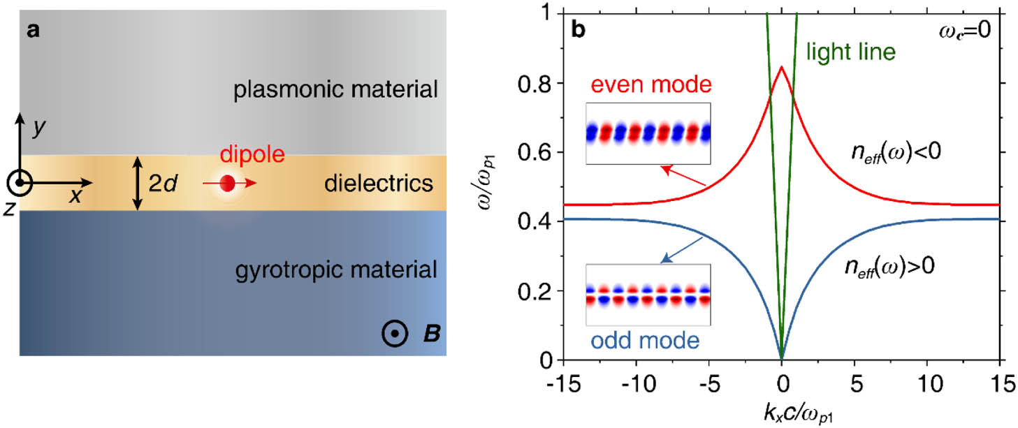
    Fig. 1. (a) Schematic diagram of the multi-channel nonreciprocal waveguide, which is composed of a plasmonic material, a dielectric, and a gyrotropic material. A static magnetic field B=Bz^ with the polarization along the z direction is applied to the gyrotropic material. A dipole with x-oriented dipole momentum is located in the center of the transparent dielectric with a thickness of 2d=50  nm. (b) Dispersion relation of the proposed waveguide when the cyclotron frequency ωc=0 (zero magnetic field). The insets are the Ex-field distribution of the odd mode and even mode, respectively.
    (a) Dispersion relation of the multi-channel nonreciprocal waveguide when the cyclotron frequency ωc=0.5ωp1 (non-zero magnetic field). There are four non-reciprocal channels, as highlighted in different colors. (bi)–(biv) Field distributions in the four non-reciprocal channels. In each nonreciprocal channel, photons from the dipole are emitted in a nonreciprocal manner.
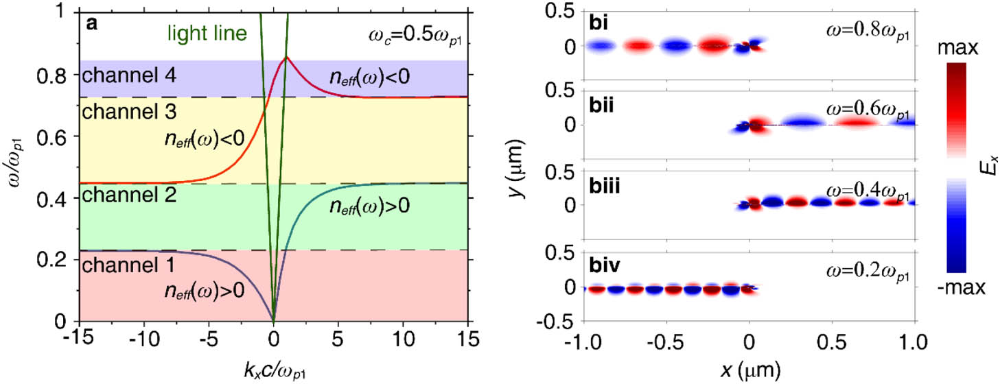
    Fig. 2. (a) Dispersion relation of the multi-channel nonreciprocal waveguide when the cyclotron frequency ωc=0.5ωp1 (non-zero magnetic field). There are four non-reciprocal channels, as highlighted in different colors. (bi)–(biv) Field distributions in the four non-reciprocal channels. In each nonreciprocal channel, photons from the dipole are emitted in a nonreciprocal manner.
    Calculated directionality of each nonreciprocal channel. D1 is the forward directionality (blue line), and D2 is the backward directionality (red line). Different channels are highlighted in different colors as in Fig. 2(a).
    Fig. 3. Calculated directionality of each nonreciprocal channel. D1 is the forward directionality (blue line), and D2 is the backward directionality (red line). Different channels are highlighted in different colors as in Fig. 2(a).
    Two schemes to separate the fundamental signal and the second harmonic using the multi-channel nonreciprocal waveguide. (ai) Schematic diagram of the first scheme: the fundamental signal in channel 1 is routed backward [see (aii)], while the second harmonic in channel 2 is routed forward [see (aiii)]. (bi) Schematic diagram of the second scheme: the fundamental signal in channel 2 is routed forward [see (bii)], while the second harmonic in channel 4 is routed backward [see (biii)].
    Fig. 4. Two schemes to separate the fundamental signal and the second harmonic using the multi-channel nonreciprocal waveguide. (ai) Schematic diagram of the first scheme: the fundamental signal in channel 1 is routed backward [see (aii)], while the second harmonic in channel 2 is routed forward [see (aiii)]. (bi) Schematic diagram of the second scheme: the fundamental signal in channel 2 is routed forward [see (bii)], while the second harmonic in channel 4 is routed backward [see (biii)].
    Calculated power density of the fundamental signal (blue line) and the second harmonic (red line) at L=1 μm away from the dipole source in (a) the first scheme and (b) the second scheme, as indicated in Fig. 4. The arrows represent the propagation direction of the corresponding EM modes.
    Fig. 5. Calculated power density of the fundamental signal (blue line) and the second harmonic (red line) at L=1  μm away from the dipole source in (a) the first scheme and (b) the second scheme, as indicated in Fig. 4. The arrows represent the propagation direction of the corresponding EM modes.
    (a) Dispersion relations of a realistic structure, where both the plasmonic material and the gyrotropic material are doped InSb, and the dielectric is replaced by the strained Si. The QD is embedded in the Si slab. A static magnetic field is applied on the InSb in the bottom layer, shown as the inset. For comparison, dispersion relations are plotted for the system under the static magnetic field B=0 T, B=0.27 T, and B=0.54 T, respectively. (b), (c) Field distributions in the fundamental frequency and in the second-harmonic frequency bands under the static magnetic field B=0.54 T, respectively.
    Fig. 6. (a) Dispersion relations of a realistic structure, where both the plasmonic material and the gyrotropic material are doped InSb, and the dielectric is replaced by the strained Si. The QD is embedded in the Si slab. A static magnetic field is applied on the InSb in the bottom layer, shown as the inset. For comparison, dispersion relations are plotted for the system under the static magnetic field B=0  T, B=0.27  T, and B=0.54  T, respectively. (b), (c) Field distributions in the fundamental frequency and in the second-harmonic frequency bands under the static magnetic field B=0.54  T, respectively.
    Hao Hu, Liangliang Liu, Xiao Hu, Dongjue Liu, Dongliang Gao. Routing emission with a multi-channel nonreciprocal waveguide[J]. Photonics Research, 2019, 7(6): 642
    Download Citation