In this Letter, we report an Airy-like beam of magnetostatic surface spin wave (AiBMSSW) supported on the ferromagnetic film, which is transferred from the optical field. The propagation properties of AiBMSSW were verified with micromagnetic simulation. From simulation results, the typical parabolic trajectory of the Airy-type beam was observed with an exciting source encoding 3/2 phase pattern. The simulation results coincide well with design parameters. Furthermore, simulated results showed that the trajectories of the AiBMSSW could be tuned readily with varied external magnetic fields. This work can extend the application scenario of spin waves.
The Airy beams[1–3], an optical corresponding form of diffraction-free wavepacket solutions of the Schrödinger equation[4], have been found in a variety of optical applications, such as optical trapping[5], self-bending plasma channels[6,7], light bullet generation[8,9], light sheet microscopy[10], tomographic microscopy[11], material processing[12], and particle manipulation[13–15] due to its peculiar properties, e.g., non-diffraction, lateral acceleration, self-bending, and self-healing. Considering the intrinsic property of waves, Airy-type oscillations have been extended to different kinds of area of wave physics, such as surface plasmons[16], electron beams[17,18], sound waves[19], and water waves[20]. Particularly, Airy function is the analytic non-diffraction form in two-dimensional (2D) space of the Schrödinger equation[4], which lead to diverse applications in surface waves, such as surface plasmon polaritons (SPPs). More details of Airy beams can be referred to in the review paper[15].
The spin wave (SW) is the wave form of electron spin state excited in ferromagnetic film. This wave propagates by means of the procession due to the exchange or dipole-dipole interactions[21]. In the past decades, SWs have been explored extensively for both fundamentally interesting and promising potential applications in high-density storage and information processing[21–26]. For massive application of SWs, methods to readily manipulate and shape SWs must be developed. However, it is not a trivial task due to diverse forms of SWs. Until now, all kinds of methods, for example, patterned or non-uniform magnetic field[21–26], varied thickness of modulated magnetic film[27], and the phase of excitation sources, have been developed to experimentally focus, guide, split, and shape SWs to match various applications.
As the aforementioned, the Airy-like oscillation has been extended to many wave forms. Of interest is whether the magnetic film supports the Airy-like SWs, or whether the SWs with parabolic trajectory can be formed with a specific design. A caustic SW beam was ever predicted and experimentally demonstrated[28,29] with a point-like source. Though Airy function was found in their theoretical result, the parabolic trajectories of their beam could not be presented directly. In this Letter, we introduced a method, borrowed from optics, to excite Airy-like oscillations in magnetic film. In optics, two methods are commonly used to generate Airy beams, i.e., Fourier transform (FT) of the cubic phase[4,30,31] and 3/2 phase pattern[32]. The FT of the cubic phase can generate high-quality Airy beams with complex optical configuration. However, due to the quick decay of SWs and additional length requirement for FT, it would be difficult to explore the propagation properties of Airy-like SWs generated with FT of the cubic phase. Meanwhile, the 3/2 phase pattern would be practical because it can excite the Airy form directly, which had been successfully adopted to generate Airy plasmon[16]. Considering the generating configuration of SWs, we design a source configuration with the 3/2 phase pattern to excite the SW and anticipate the parabolic propagation trajectory on the magnetic film. The propagation properties of the Airy-like SW were verified with numerical simulation based on micromagnetic software Mumax3, which has been extensively adopted to simulate SWs. In our knowledge, this result is the first demonstration of the Airy-like SW with parabolic trajectories. We even anticipate that this novel Airy wave would open a new scenario for both SWs and Airy-type waves, similar to the research climax when introducing “Airy” into plasmonics.
Sign up for Chinese Optics Letters TOC. Get the latest issue of Chinese Optics Letters delivered right to you!Sign up now
As we know, there are several types of SWs that can be excited with various magnetic field configurations[26]. For example, the forward-volume magnetostatic SWs (FVMSWs) would be excited when the direction of the applied magnetic field is perpendicular to the ferromagnetic film. If the applied magnetic field is parallel to the film surface, two modes would be found. One is called the backward-volume magnetostatic SW (BVMSW), where the wave vector would be parallel to the magnetic field. The other is called the magnetostatic surface SW (MSSW), where the wave vector is perpendicular to the magnetic field. Both wave vectors of these two modes are parallel to the surface of film. In this Letter, a 2D form Airy-type wave was focused, so MSSWs were considered for simulation. Simulation results verified the parabolic trajectory of MSSWs on magnetic film, i.e., the Airy-like beam MSSWs (AiBMSSWs) can be effectively generated with this design. Furthermore, the simulation results also showed that the parabolic trajectory of AiBMSSWs could be effectively tuned by an external magnetic field.
2. Simulation Configuration
In this work, we focused on the MSSW, which shows a surface wave behavior. The dispersion relation of the MSSW is expressed as[33,34]πwhere is the frequency of the wave, is the vacuum permeability, is the gyromagnetic ratio , is the external magnetic field, is the saturation magnetization, is the wavevector of the SW, and is the thickness of the magnetic film. According to the dispersion relation, the wavelength of the MSSW can be determined by given parameters, which are important for coding the phase pattern in the excitation source. Though the vector of the SW would be complex for Airy-like beams, this dispersion relation can also determine the wavelength range for simulation[34].
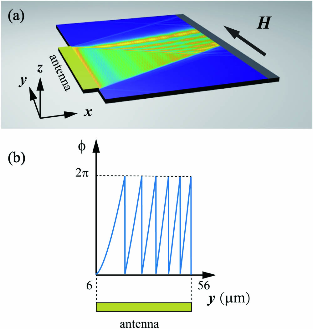
To numerically simulate the AiBMSSWs, micromagnetic simulation software MuMax3[35] was used. Figure 1(a) shows the schematic for simulation. The simulation region (Permalloy magnetic film) is μ wide and μ long to ensure enough area for reconstructing an Airy profile limited by the approximation of the 3/2 phase. The thickness of the film is set as 30 nm. The simulation cell size is set as to ensure the accuracy of the results. The wavelength of the AiBMSSW is much larger than both the cell size and the exchange length. In our model, any impact of the exchange interaction is unrelated, as shown in Ref. [36]. Typical material parameters of Permalloy[37] were adopted: saturation magnetization , exchange stiffness , and Gilbert damping . A bias magnetic field is applied along the axis.
Figure 1.(a) Schematic for micromagnetic simulation and (b) phase pattern of the excitation antenna.
A strip metal antenna (μμ) is used to excite the SWs at the left edge, as shown in Fig. 1(a). When this antenna is driven with the local magnetic field () along the direction, an SW (μ) propagating along the direction can be excited. The wavelength of the SW is achieved with dispersion relation and simulation results. In this work, the form of the RF magnetic field is π. To avoid interference from reflected waves, a high-damping () area ranged in μμ is set to fully absorb the propagating SW.
The phase of excitation source is encoded with the 3/2 phase as shown below:πwhere is the parameter to determine the parabolic curve, is the wavelength of the wave, and is the abscissa. The trajectory of the Airy wave is approximately a parabola, and the trajectory equation is . The length of the excitation source is . The value of is determined by the wavelength and length , while ensuring that the phase distribution of the excitation source is constant (details can be found in Refs. [32,38]).
The phase distribution of the antenna region is initialized with Eq. (2). In the antenna region, 200 sub-regions were defined in MuMax3. Each sub-region has a length of and a width of μ. Figure 1(b) shows the phase profile of the excitation antenna of SWs, which is a wrap phase (2π) according to Eq. (2), i.e., π, where mod(·) denotes the modulus operation.
3. Simulation Results
Figures 2(a)–2(c) show the time-varied snapshots of the component of the reduced dynamic magnetization () when SWs propagate on the magnetic film, where is the magnetization in the direction. Due to the damping, the propagation properties of would be very unclear. So, normalized distribution of is shown in the inset of Fig. 2(c). It can be seen that the wavefront of MSSWs is gradually shifting to the negative direction of the y axis with a time elapse. However, the bound of energy distribution is deflected toward the positive direction of the y axis, which agreed with the anticipation of deflecting direction of the designed Airy-like beam.
Figure 2.Snapshots of mz distribution at (a) 5 ns, (b) 10 ns, and (c) 15 ns. Parameters are set as a = μ, l = μ. The inset of (c) shows the normalized mz.
To verify the Airy-like behavior clearly, the time-average intensity of magnetization should be considered. The intensity of the SW is calculated according to the equation[21], as shown in Fig. 3(a). The simulating parameters were set as μ and μ. Similar to the distribution, the intensities were normalized with the transverse maximum value. It can be seen from both Figs. 3(a) and 3(c), the main lobe of the SW followed a parabolic trajectory apparently. According to calculation, within μ propagation distance, the deflections of the main lobe of SWs are about μ and μ in Figs. 3(a) and 3(c), respectively. The green lines show fitting trajectories of the main lobes of AiBMSSWs in Figs. 3(a) and 3(c). In conclusion, the proposed design with the 3/2 phase pattern can generate AiBMSSWs effectively.
Figure 3.Time-averaged SW relative intensity distribution with (a) a = μ and (c) a = μ; (b), (d) corresponding cross-section profiles along the dashed lines in (a) and (c).
Figure 3(b) shows the profiles of the intensity of the dashed line along the axis in Fig. 3(a). With longer propagation distance, the profiles of intensity are similar with Airy-function profiles, which can be ascribed to a slowly varied phase near the origin, as explained in Ref. [32]. Figures 3(c) and 3(d) show similar intensity distributions as those in Figs. 3(a) and 3(b) except a different μμ value. The insets in Figs. 3(a) and 3(b) showed the corresponding intensity distribution of AiBMSSWs without normalization.
Next, more AiBMSSWs with different trajectories were simulated, as shown in Fig. 4(a). The designed values of are set as μ. The values fitted with simulation results are μ, which are very close to the designed values. The corresponding deflection distances of main lobe of AiBMSSWs are μ, while SWs propagate a μ distance. Figure 4(b) shows the propagation trajectories of SWs generated with linear phase (0–37.6 rad) instead of 3/2 phase modulation on the excitation source. The main lobe of SWs propagates along a slant, but not a parabola. This further confirms the validity of our design for AiBMSSWs generation.
Figure 4.(a) Numerical simulation and fitting propagation trajectories for AiBMSSW with different deflection factors, a = μ; (b) intensity distribution of SWs generated with linear phase modulation.
As shown in Eq. (1), the frequency (wavelength) of SWs will vary with different external magnetic fields (). Consequently, referring to Eq. (2), , the key parameter to characterize the parabola, will be tuned with changing. This mechanism provides an approach to tune the trajectory of AiBMSSWs via an external field. The numerical simulation was also performed to validate this envision. In the simulation, a bias magnetic field along the direction [labelled as in Fig. 1(a)] was adopted. Figure 5 shows the simulation results with the magnetic field varying from 25 mT to 35 mT. As depicted in Fig. 5, with the same phase distribution on the excitation source, the curvature of trajectories of AiBMSSWs is increased with larger magnetic fields, which means that the larger the magnetic field, the larger the deflection of AiBMSSWs. This effect can be explained by revisiting Eq. (2). When the wavelength [denominator of right side of Eq. (2)] increased, and the phase () and [part of the nominator on the right side of Eq. (2)] stayed fixed, [part of the nominator on the right side of Eq. (2)] must be increased and leads to a large curvature of trajectory of AiBMSSWs. In Fig. 5, the calculated values of are μ. Correspondingly, the deflections of AiBMSSWs were tuned from μ to μ with a μ propagation distance.
Figure 5.Trajectories of AiBMSSWs with various magnetic fields.
In conclusion, we have numerically shown how to generate AiBMSSWs with the 3/2 phase pattern encoded onto the excitation source. Simulation results with micromagnetic software MuMax3 validate the effectiveness of this method, and the fitting trajectory parameters agree well with designed parameters. Furthermore, numerical results also show that the trajectories of AiBMSSWs can be effectively tuned with an external magnetic field, which provide an additional degree of freedom for application of SWs. In practice, the 3/2 phase modulation can be binarized and achieved with varied ferromagnetic film thickness, which will be a solution for generating AiBMSSWs experimentally due to the mature micro-fabrication technology. In addition, the design for Airy-like beam generation in MSSWs should be effective for other types of SWs, such as the exchange of SWs (ESWs) and FVMSWs. The proposed method in this work would pave a way to achieve special beams in SWs, which would benefit further developments in magnonics and planar SWs “optics”.