
Guangming Li, Gangxian Zhu, Jiaqiang Li, Shihong Shi. Experimental Study on Thin Walls by Laser Additive Manufacturing Based Inside-Beam Powder Feeding with Variable Posture[J]. Laser & Optoelectronics Progress, 2023, 60(1): 0114008
- Laser & Optoelectronics Progress
- Vol. 60, Issue 1, 0114008 (2023)
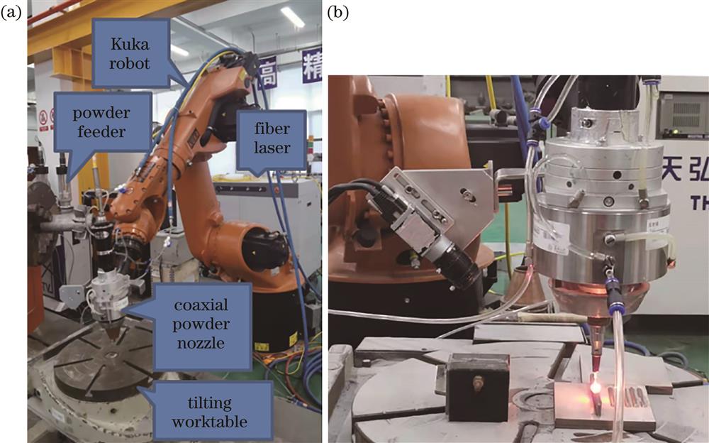
Fig. 1. Experimental device. (a) Additive manufacturing system; (b) location of CCD camera
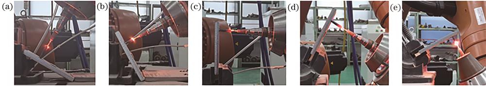
Fig. 2. Schematic of substrate tilt angle. (a) θ=30°; (b) θ=60°; (c) θ=90°; (d) θ=120°; (e) θ=150°
Fig. 3. Thin-walled parts with different inclination angles. (a) θ=0°; (b) θ=30°; (c) θ=60°; (d) θ=90°; (e) θ=120°; (f) θ=150°
Fig. 4. Tail collapse angles of formed thin-walled parts under different inclination angles
Fig. 5. Forming dimensions of thin wall with different substrate inclination angles. (a) Overall height of forming part; (b) width of forming part and length of molten pool
Fig. 6. Comparison of width and molten pool length with different substrate inclination angles. (a) θ =0°;(b) θ =30°; (c) θ =60°; (d) θ =90°; (e) θ =120°; (f) θ =150°
Fig. 7. Proportion of shadow area in the molten pool to the molten pool area with different substrate inclination angles. (a) Diagram of molten pool area and shadow area; (b) proportion of shadow area in molten pool
Fig. 8. Force analysis diagram of molten pool
Fig. 9. Single cross-sectional contour curves under different inclination angles
Fig. 10. Additional pressure on curved surface
Fig. 11. Relationship between additional pressure and radius of curvature
Fig. 12. Schematic of additional pressure on surface tension of molten pool
|
Table 1. Process parameters of laser additive manufacturing experiment

Set citation alerts for the article
Please enter your email address
© Copyright 2018-2021 | Chinese Laser Press. All Rights Reserved 沪ICP备15018463号-20