
Chentianfei Shen, Tong Shen, Qi Chen, Qinghan Zhang, Jihong Zheng, "Machine-learning-based high-speed lensless large-field holographic projection using double-sampling Fresnel diffraction method," Chin. Opt. Lett. 20, 050502 (2022)
- Chinese Optics Letters
- Vol. 20, Issue 5, 050502 (2022)
Abstract
1. Introduction
Focus cues, image quality, field of view (FOV), and eye box are key issues in near-eye displays such as virtual reality and augmented reality[
The Nyquist criterion limits the size of the reconstructed image when employing a standard diffraction method in computational holography, either the Fresnel diffraction algorithm or the Fraunhofer diffraction algorithm[
To overcome the aforementioned FOV and time-consuming issues, we present a method combining the machine-learning-based technique with the lensless holographic projection. This method is based on the double-sampling Fresnel diffraction (DSFD) algorithm[
Sign up for Chinese Optics Letters TOC. Get the latest issue of Chinese Optics Letters delivered right to you!Sign up now
2. Methods
In a holographic display system, finding the phase value
We discuss an intuitive reason for the use of the DSFD algorithm as the light propagation function. In a near-eye display system, a large FOV is a vital factor and is determined from the holographic image projection. We evaluate several lensless light propagation algorithms, including the S-FFT, the angular spectrum method (ASM), the DSFD, and the three-step diffraction[
![]()
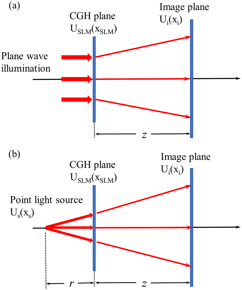
Figure 1.Principle of S-FFT and DSFD algorithms for lensless holographic projection. (a) S-FFT algorithm with plane wave illumination; the maximum projecting image size is limited by the Nyquist criterion. (b) DSFD algorithm with diverging point light source; the image size is larger.
Figure 1(a) shows the scheme of CGH calculation for the S-FFT algorithm. The complex amplitude distribution
The image size of S-FFT algorithm
Here,
As depicted in Fig. 1(b), the diverging spherical wave propagates through two planes, the first plane is the hologram plane, and the second one is the image plane. According to the Fourier optics, the propagation of the light wave can be regarded as two steps. In the first step, since the SLM is illuminated by a diverging light wave, the procedure from the hologram plane to the point light source can be taken as the inverse Fraunhofer diffraction. The complex amplitude distribution
Since the Fourier transform is used in the above diffraction procedures, the sampling interval should be calculated according to
The maximal size of the diffraction image is determined by
The use of the diverging wave as the light source may enlarge the image sizes with a ratio depending on the relation of
![]()
Figure 2.Projection image size of the S-FFT algorithm and DSFD algorithm, where the wavelength is 532 nm, pixel size is 8 µm, the number of pixels is 1920, and the distance between the point light source and the SLM plane is 2.6 cm.
The procedure for calculating the resulting light field on the image plane is shown in Eq. (5). Evidently, the complex amplitude representation on the SLM plane is required to display such holograms. Usually, SLMs are classified into phase-only, amplitude-only, and complex amplitude modulation types. Aside from availability, phase-only SLMs are often preferred because of their high light efficiency. Notably, light is only steered but not attenuated. Nevertheless, calculating holograms that function with phase-only SLMs is one of the main challenges in developing holographic displays. The common method to encode the complex amplitude CGH into phase-only CGH is an iterative phase optimization. The iterative Gerchberg–Saxton (GS) algorithm is the standard way to solve the problem of phase retrieval of a field on two separate planes, as shown in Fig. 3. Unfortunately, the GS algorithm inevitably requires long computation time and leads to serious speckle noise in the image reconstruction.
![]()
Figure 3.GS algorithm workflow for computing a phase-only CGH from target image.
In order to further improve the image quality and reduce the calculating time of the CGH, the method based on the combination of the DSFD algorithm and machine learning is proposed. Gradient descent is a way to minimize an objective function parameterized by a model’s parameters by updating the parameters in the opposite direction of the gradient of the objective function to the parameters. We first implement stochastic gradient descent (SGD) to optimize the loss function in Eq. (1); see Fig. 4. We give an initial random phase on the SLM plane and calculate the complex field on the image plane with the DSFD algorithm. Then, we calculate the loss between the target image and the simulated projection image. Finally, we backpropagate the error between the target images and simulate reconstruction with a stochastic descent optimization algorithm to update the phase-only holograms. Since the iterative procedure of the SGD does not perform the inverse calculation of the light propagation and only needs to calculate the diffraction once, time consumption is only half of the traditional GS method for each epoch. In addition, by adjusting the learning rate, the SGD algorithm converges much faster than the traditional GS method.
![]()
Figure 4.SGD algorithm workflow for computing a phase-only CGH from target image.
Despite the fact that the SGD algorithm can reduce the computation time of holograms by more than half, we still need a fast way to obtain the phase-only hologram. We then combine the above DSFD algorithm with a neural network to form our DSFD-Net model. The DSFD-Net model can be trained in an unsupervised learning method of the mapping from the target image to the hologram without labels. The generation and reconstruction of phase-only CGH can be depicted as the encoding and decoding process of target images. Our neural network works as the encoder part in the system and translates the target image to the corresponding phase-only CGH. The output of the network is the input of our decoder. The decoding part is the fixed DSFD model that has been described above. The architecture of our training procedure and the U-Net is shown in Fig. 5. As an unsupervised learning model, the data sets and validation sets do not need to be labeled.
![]()
Figure 5.Illustration of our wave propagation model. A target image is first converted to an amplitude value, and then is passed to a phase-encoder network (i.e., the U-Net). At the SLM plane, we display the CGH and propagate the light field to the target plane. During the training phase, the loss between the projection image and the target amplitude can be calculated and is then propagated back to train the phase-encoder network.
The U-Net model uses a down-sampling and then up-sampling structure. The use of a skip connection at the same stage ensures that the final CGH output incorporates more low-level features and retains all the information in the image. This advantage is very suitable for CGH computation. The length and width of the image tensor are reduced by half after each down-sampling in our U-Net, and the geometric feature extraction of the input image is realized after down-sampling is repeated six times. When the up-sampling of next six times is implemented, the reconstructed original size image tensor is obtained. In order to avoid the disappearance of the gradient during the network training, the residual connection is employed to realize the cross-layer transfer of the gradient. After each convolution, batch normalization is performed to avoid overfitting. In the U-Net training procedure, we use the amplitude of the
3. Simulation
We simulate the light propagation on Google Colab with PyTorch, which is essentially based on python and compute unified device architecture (CUDA), to demonstrate the performance of different algorithms with graphics processing units (GPUs). The GPU is NVIDIA Tesla P100 with 16 GB memory. To keep consistent with the experimental situation, the pixel pitch of the CGH is set as 8 µm, and the resolution is
![]()
Figure 6.Performance evaluation of the GS algorithm and the SGD algorithm.
A gray-level image in Fig. 7 is employed to demonstrate the effectiveness of our U-Net. A comparison between the U-Net and iterative methods demonstrates that the proposed U-Net method produces the reconstructed images with acceptable quality. The PSNR is more than 23 dB.
![]()
Figure 7.Performance evaluation of our U-Net and the iterative methods. The PSNR and MSE values indicate the reconstruction image quality of the algorithm.
The numerical reconstructions are presented in Fig. 8. We test 100 random images from the testing dataset, and Fig. 8(a) indicates that both the GS and SGD iterative algorithms can achieve a high quality (
![]()
Figure 8.Comparison of average calculating speed and image quality achieved by several CGH techniques. (a) Images are reconstructed with similar quality at the same number of iterations by GS and SGD algorithms. (b) The SGD algorithm requires less time than the GS algorithm for high-quality reconstruction. The U-Net takes less than 0.05 s, which is far less than that of iterative methods. The horizontal of Fig. 8(b) is in logarithmic scale.
4. Experiments
We also build an actual phase-only holographic display prototype to validate our simulation results. All of the experiments are performed under the same condition. The schematic of the experimental setup is shown in Fig. 9. We load the CGH on a HOLOEYE PLUTO-2-VIS-014 reflective SLM. The pixel size of the SLM is 8 µm, and the pixel number is
![]()
Figure 9.Schematic of the experimental setup (P1, P2, polarizers; C&E, collimator and expander; L, lens; BS, beam splitter).
Figure 10 demonstrates the effectiveness of our proposed method. The simulated image and the experimental result of our U-Net are shown in Fig. 10(a). The size of the projection image on the wall is
![]()
Figure 10.(a) Simulated optical image and the experimental result based on U-Net. (b) Comparison of reconstruction quality of different encoding methods.
The results show that our DSFD-Net model has great potential for designing a lensless holographic projection system with large FOV. Besides, current methods using machine learning for calculating the diffraction process are basically for simple diffraction algorithms, such as the S-FFT algorithm and the angular spectrum diffraction algorithm. For different tasks, the corresponding machine learning methods and systems have their own adaptations. Whether machine learning algorithms can be applied to more complex algorithms such as the DSFD algorithm is still unknown. In this paper, we use machine learning for DSFD algorithms with calculation of multiple diffraction processes and varying sampling frequencies to demonstrate that machine learning can be applied to different types of diffraction algorithms and that the corresponding CGHs can be calculated in real time. However, the proposed method still has some unsolved issues. For example, training a digital hologram of a high-resolution image using a convolutional neural network requires a very large GPU memory size. At the current stage, it is difficult for the proposed method to further increase the image resolution with available GPUs. In the next work, we will try to compress the size of the neural network and find other network structures to adapt our method to higher resolution images. In the future, we will continue to study the algorithm of CGH, especially 3D digital holography based on machine learning.
5. Discussion
In this paper, the machine learning techniques are introduced to generate the hologram used in an image magnified lensless holographic projection system. Compared to the iterative method, neural network can compress computation time to the several milliseconds level. Meanwhile, the neural network can match various projection systems to meet the corresponding requirement of the near-eye display devices. The proposed method is applicable to augmented reality displays, virtual reality displays, and, hopefully, other real-time 3D display systems in the future.
References
[1] T. Zhan, K. Yin, J. Xiong, Z. He, S. T. Wu. Augmented reality and virtual reality displays: perspectives and challenges. iScience, 23, 101397(2020).
[2] K. Yin, Z. He, J. Xiong, J. Zou, K. Li, S.-T. Wu. Virtual reality and augmented reality displays: advances and future perspectives. J. Phys. Photonics, 3, 022010(2021).
[3] B. C. Kress, P. Schelkens. Optical waveguide combiners for AR headsets: features and limitations. Proc. SPIE, 11062, 110620J(2019).
[4] C. Chang, K. Bang, G. Wetzstein, B. Lee, L. Gao. Toward the next-generation VR/AR optics: a review of holographic near-eye displays from a human-centric perspective. Optica, 7, 1563(2020).
[5] A. Maimone, A. Georgiou, J. S. Kollin. Holographic near-eye displays for virtual and augmented reality. ACM Trans. Graph., 36, 85(2017).
[6] P. Sun, S. Chang, S. Liu, X. Tao, C. Wang, Z. Zheng. Holographic near-eye display system based on double-convergence light Gerchberg–Saxton algorithm. Opt. Express, 26, 10140(2018).
[7] Y. Peng, S. Choi, N. Padmanaban, G. Wetzstein. Neural holography with camera-in-the-loop training. ACM Trans. Graph., 39, 185(2020).
[8] J. Wu, K. Liu, X. Sui, L. Cao. High-speed computer-generated holography using an autoencoder-based deep neural network. Opt. Lett., 46, 2908(2021).
[9] R. Horisaki, R. Takagi, J. Tanida. Deep-learning-generated holography. Appl. Opt., 57, 3859(2018).
[10] Y. Zhao, L. Cao, H. Zhang, D. Kong, G. Jin. Accurate calculation of computer-generated holograms using angular-spectrum layer-oriented method. Opt. Express, 23, 25440(2015).
[11] Z. He, X. Sui, G. Jin, L. Cao. Progress in virtual reality and augmented reality based on holographic display. Appl. Opt., 58, A74(2019).
[12] S. J. Liu, D. Xiao, X. W. Li, Q. H. Wang. Computer-generated hologram generation method to increase the field of view of the reconstructed image. Appl. Opt., 57, A86(2018).
[13] F. Yaras, H. Kang, L. Onural. Circular holographic video display system. Opt. Express, 19, 9147(2011).
[14] R. Kang, J. Liu, G. Xue, X. Li, D. Pi, Y. Wang. Curved multiplexing computer-generated hologram for 3D holographic display. Opt. Express, 27, 14369(2019).
[15] S. J. Liu, N. T. Ma, F. X. Zhai, N. N. Liu, P. P. Li, Y. Q. Hao, D. Wang. Large field-of-view holographic display method with speckle noise suppression based on time multiplexing. J. Soc. Inf. Disp., 29, 758(2021).
[16] C. Chang, Y Qi, J. Wu, J. Xia, S. Nie. Image magnified lensless holographic projection by convergent spherical beam illumination. Chin. Opt. Lett., 16, 100901(2018).
[17] W. Qu, H. Gu, H. Zhang, Q. Tan. Image magnification in lensless holographic projection using double-sampling Fresnel diffraction. Appl. Opt., 54, 10018(2015).
[18] K. Wang, Q. Kemao, J. Di, J. Zhao. Y4-Net: a deep learning solution to one-shot dual-wavelength digital holographic reconstruction. Opt. Lett., 45, 4220(2020).
[19] F. Niknam, H. Qazvini, H. Latifi. Holographic optical field recovery using a regularized untrained deep decoder network. Sci. Rep., 11, 10903(2021).
[20] J. Tang, J. Wu, K. Wang, Z. Ren, X. Wu, L. Hu, J. Di, G. Liu, J. Zhao. RestoreNet-Plus: image restoration via deep learning in optical synthetic aperture imaging system. Opt. Lasers Eng., 146, 106707(2021).
[21] H. Pang, A. Cao, W. Liu, L. Shi, Q. Deng. Effective method for further magnifying the image in holographic projection under divergent light illumination. Appl. Opt., 58, 8713(2019).


Set citation alerts for the article
Please enter your email address

© Copyright 2018-2021 | Chinese Laser Press. All Rights Reserved 沪ICP备15018463号-20