• Chinese Optics Letters
  • Vol. 17, Issue 3, 030601 (2019)
Xihua Zou*, Peixuan Li, Wei Pan, and Lianshan Yan
Author Affiliations
  • School of Information Science and Technology, Southwest Jiaotong University, Chengdu 611756, China
  • show less
    DOI: 10.3788/COL201917.030601 Cite this Article Set citation alerts
    Xihua Zou, Peixuan Li, Wei Pan, Lianshan Yan. Photonic microwave filters with ultra-high noise rejection [Invited][J]. Chinese Optics Letters, 2019, 17(3): 030601 Copy Citation Text show less
    Three structures for PMF design. (a) PMF operating at the coherent regime; (b) PMF operating at the incoherent regime; (c) PMF based on the mapping of optical response. (E/O, electro-optic conversion; PD, photodetector.)
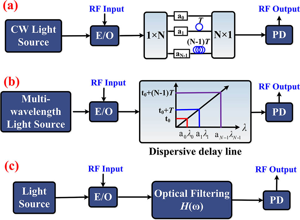
    Fig. 1. Three structures for PMF design. (a) PMF operating at the coherent regime; (b) PMF operating at the incoherent regime; (c) PMF based on the mapping of optical response. (E/O, electro-optic conversion; PD, photodetector.)
    Operation principle for the bandstop PMFs based on the RF cancellation technique.
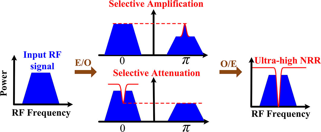
    Fig. 2. Operation principle for the bandstop PMFs based on the RF cancellation technique.
    Schematic diagram of the bandpass PMF with ultra-high ORR when using the amplified recirculating delay line and windowing technique. (OFS, optical frequency shifter; WDE, wavelength-dependent element; PD, photodetector.)
    Fig. 3. Schematic diagram of the bandpass PMF with ultra-high ORR when using the amplified recirculating delay line and windowing technique. (OFS, optical frequency shifter; WDE, wavelength-dependent element; PD, photodetector.)
    Schematic diagram of bandpass PMF with ultra-high ORR when using a Gaussian-shaped optical frequency comb (OFC).
    Fig. 4. Schematic diagram of bandpass PMF with ultra-high ORR when using a Gaussian-shaped optical frequency comb (OFC).
    Operation principles for the bandpass PMFs: the direct spectrum mapping (top) and phase modulation to intensity modulation (PM-IM) conversion (bottom). (OC, optical carrier; OBPF, optical bandpass filter; ONF, optical notch filter.)
    Fig. 5. Operation principles for the bandpass PMFs: the direct spectrum mapping (top) and phase modulation to intensity modulation (PM-IM) conversion (bottom). (OC, optical carrier; OBPF, optical bandpass filter; ONF, optical notch filter.)
    Operation principle of the bandpass PMF using the polarization modulation and polarization pulling effect. Optical spectra of polarization modulation when (a) switching off or (c) switching on the SBS processing. RF spectral responses of the PMF when (b) switching off or (d) switching on the SBS processing. x and y represent two orthogonal polarization states. ΩB is the Brillouin frequency shift. OC, optical carrier; O/E, optic-electronic conversion.
    Fig. 6. Operation principle of the bandpass PMF using the polarization modulation and polarization pulling effect. Optical spectra of polarization modulation when (a) switching off or (c) switching on the SBS processing. RF spectral responses of the PMF when (b) switching off or (d) switching on the SBS processing. x and y represent two orthogonal polarization states. ΩB is the Brillouin frequency shift. OC, optical carrier; O/E, optic-electronic conversion.
    Measured RF response of the bandpass PMF with a record high ORR of 80 dB.
    Fig. 7. Measured RF response of the bandpass PMF with a record high ORR of 80 dB.
    PMFs (Ref.)CategoryCenter Frequency or Frequency Coverage (GHz)3-dB Bandwidth (MHz)Rejection Ratio (NRR, dB)
    [10]Periodic10–4048
    [11]Periodic0.4>40
    [12]Periodic23.68–24.0849
    [9]Periodic0–5050
    [13]Periodic0–12>45
    [14]Single0–202500–950041
    [15]Single2–2038>50
    [16]Single2–152051
    [17]Single1–3010>60
    [18]Single2–203142
    [19]Single14–209848
    [20]Single0–3033–88>55
    [21]Single12.4–30.612,500>60
    [22]Single2–8250–84060
    [23]Single0–12150–350>50
    [31]Single2–17240/43045
    Table 1. Selected Bandstop PMFs with Rejection Ratio Higher than 40 dB
    PMFs (Ref.)CategoryCenter Frequency or Frequency Coverage (GHz)3-dB Bandwidth (MHz)Rejection Ratio (ORR, dB)
    [24]Periodic0.140.4452/70
    [25]Periodic9.38170–80062/70
    [26]Periodic0–2055
    [27]Periodic0.05–0.250
    [28]Periodic1.1–1.250.0375>40
    [29]Periodic15–202.4541
    [30]Single0–2090>40
    [32]Single0–1274041
    [33]Single0–101000–300057
    [34]Single9.250–200>49
    [35]Single2.933.1570
    [36]Single10045
    [37]Single11.565070
    [38]Single65077
    [39]Single0–401655
    [42]Single1.6–2.15250–100044/46
    [41]Single0–1842.1>60
    [40]Single2.1–6.17.780
    Table 2. Selected Bandpass PMFs with an Out-of-band Rejection Ratio Higher than 40 dB
    Xihua Zou, Peixuan Li, Wei Pan, Lianshan Yan. Photonic microwave filters with ultra-high noise rejection [Invited][J]. Chinese Optics Letters, 2019, 17(3): 030601
    Download Citation