As a key figure-of-merit for high-performance microwave filters, the out-of-band noise rejection is of critical importance in a wide range of applications. This paper overviews the significant advances in photonic microwave filters (PMFs) having ultra-high rejection ratios for out-of-band noise suppression over the last ten years. Typically, two types of PMFs, the bandpass and bandstop ones, are introduced with fundamental principles, detailed approaches, and then cutting-edge results for noise rejection. Ultra-high noise rejection ratios of ~80 dB and >60 dB have been demonstrated for single-passband and single-stopband PMFs, respectively, which are comparable with the state-of-the-art electronic filters operating in stringent conditions. These PMFs are also characterized by wide frequency coverage, low frequency-dependent loss, and strong immunity to electromagnetic interference due to the intrinsic features from the advanced photonics technology.
Assisted by advanced photonic techniques, photonic microwave filters (PMFs) enable the processing of microwave signals in the optical domain, harnessing advantages including large instantaneous bandwidth, low frequency-dependent loss, flexible tunability, and strong immunity to electromagnetic interference[1–7]. Thus, PMFs have been regarded as a promising alternative for pure electronic filters when facing speed and bandwidth limitations originating from the electronic bottleneck[7]. On the other hand, PMFs still have some weaknesses to be overcome, such as the out-of-band noise rejection and spectral resolution, compared with electronic filters. For instance, the conventional electronic cavity filters used in cellular base stations require an out-of-band rejection ratio (ORR) of no less than 80 dB[8].
Fortunately, over the past years, a host of significant advances in PMFs have been demonstrated, involving multiple functionalities, enhanced figure-of-merit improvements, and device integration. Here, the out-of-band noise rejection, as a significant figure-of-merit, has been greatly improved to beyond that of pure electronic filters. Accordingly, this paper summarizes the advances in PMFs with ultra-high out-of-band noise rejection. Specifically, we focus on the PMFs with a 3 dB bandwidth below 10 GHz, which is typically expected to provide high resolution in the microwave photonics field.
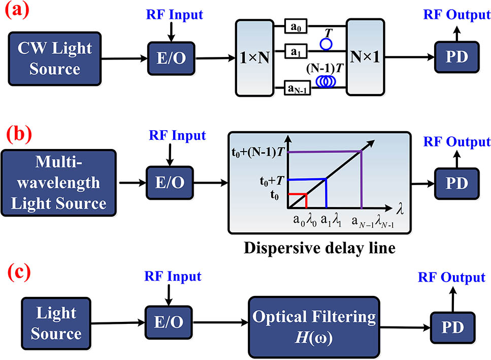
Principles of PMFs. Basically, the PMFs can be categorized as two types operating at the coherent and incoherent regimes[7], as shown in Figs. 1(a) and 1(b). Multi-tap delay lines or dispersive elements are employed to introduce time delays among taps in the optical domain. Consequently, classic finite-impulse response (FIR) or infinite-impulse response (IIR) can be generated for PMFs as[7]where denotes the radio-frequency (RF) angular frequency, and are the weighted coefficients of the th tap, and is the time delay between two adjacent taps.
Figure 1.Three structures for PMF design. (a) PMF operating at the coherent regime; (b) PMF operating at the incoherent regime; (c) PMF based on the mapping of optical response. (E/O, electro-optic conversion; PD, photodetector.)
Figure 1(c) shows another structure for designing PMFs, where the optical response of an optical filter is faithfully mapped to the microwave response. Here, different modulation formats can be used, including the single-sideband and double-sideband intensity modulation (IM)[2] or phase modulation (PM)[7].
Based on these three structures, PMFs fueled by different kinds of optical sources, electro-optic modulators, optical delay lines, and optical filters, have been demonstrated to create distinct 3 dB bandwidths, spectral resolution, out-of-band noise rejection ratios, and so on.
Bandstop PMFs with ultra-high notch rejection. Bandstop microwave filters are widely required in many systems to suppress undesired noises or interferences. First, bandstop PMFs operating at the incoherent regime can be implemented to have one or more transmission notches at specific frequencies via the use of a simple two-tap FIR structure. The notch rejection ratio (NRR) is determined by the electrical power ratio () between two taps, given by[9]
From Eq. (2), it is clear that an ultra-high NRR can be achieved by delicately manipulating the amplitudes of two recovered RF replicas experiencing different time delays[9–13]. In Ref. [10], two incoherent optical carriers from two free-running lasers were used to carry the RF signal, and two fiber paths with different physical lengths were designed as delay lines. A more than 48 dB NRR was achieved in the presence of balanced output powers of the two lasers. In addition, flat passband can be achieved by tailoring the tap amplitudes[11], accompanied with a slightly degraded NRR over 40 dB. To reduce the complexity of the light source, a two-tap PMF based on a single laser source and a Sagnac loop interferometer comprising an off-loop-center electro-absorption modulator was proposed[12], where an up to 49 dB NRR was observed. Moreover, Ref. [9] proposed a photonic crystal delay line with a chip-size footprint to realize the bandstop PMF. By exploiting the group index disparity between two orthogonal polarization modes (i.e., TE and TM modes) of a photonic crystal delay line, a two-tap bandstop PMF with a 50 dB NRR was demonstrated.
For the PMFs operating at the coherent regime, an intuitive approach to achieve a high NRR is to design a high-performance optical notch filter with an outstanding notch rejection and then transfer the optical filtering response to the RF domain. For instance, Dong et al. fabricated an optical notch filter based on cascaded microring resonators for implementing the bandstop PMF[14]. The IM was employed to perform the filtering response mapping. Consequently, a 45 dB NRR was achieved. However, when a higher NRR (e.g., ) is required, fabrication of such a stable optical notch filter could be very challenging. A more cost-effective method based on the RF cancellation technique is widely adopted to design high-performance bandstop PMFs[15–23]. The operation principle is illustrated in Fig. 2[17,21]. By applying an RF signal, a double-sideband modulation is implemented, and the resultant optical spectrum is tailored to have unequal amplitudes between the upper and lower sidebands and an out-of-phase relationship of 180°. Afterwards, an optical filtering operation (selective amplification or attenuation) is implemented to enable the upper and lower sidebands to have the same amplitude. After the optic-electro (O/E) conversion, destructive interference would occur for the generated beat notes between the sidebands and optical carrier due to the out-of-phase relationship between the upper and lower sidebands. The beat notes for the undesired RF components would be completely canceled due to the equal amplitudes, while those for the target components still survive because of the unequal amplitudes. Thus, an ultra-high NRR can be expected. Therefore, tailoring the RF-induced optical spectrum is considered another simple and effective solution to achieve an extraordinary NRR for bandstop PMFs.
Figure 2.Operation principle for the bandstop PMFs based on the RF cancellation technique.
For example, we had employed the fiber-based stimulated Brillouin scattering (SBS) effect in the PMFs to perform narrow-band amplification and thus to achieve NRRs beyond 50 dB[15,16]. Then, a 60 dB NRR was achieved in Ref. [17]. Besides the fiber-based system, the on-chip SBS effect was explored to achieve such a bandstop PMF with an NRR as high as 48 dB[19] and 60 dB[20]. Also, optical passive notch filters can be applied to implement selective attenuation for implementing the bandstop PMFs, including the silicon-on-insulator and ring resonators[21–23]. The achieved NRR reached the level of 60 dB.
A comprehensive collection on reported bandstop PMFs with a rejection ratio greater than 40 dB is listed in Table 1. Along with the NRR emphasized in this paper, other key specifications for the bandstop PMFs are also demonstrated, including the single/periodic stopband, center frequency or frequency coverage, and 3 dB bandwidth. Generally, it is more challenging to achieve the same NRR for a single stopband in contrast to the periodic one.
PMFs (Ref.)
Category
Center Frequency or Frequency Coverage (GHz)
3-dB Bandwidth (MHz)
Rejection Ratio (NRR, dB)
[10]
Periodic
10–40
–
48
[11]
Periodic
0.4
–
>40
[12]
Periodic
23.68–24.08
–
49
[9]
Periodic
0–50
–
50
[13]
Periodic
0–12
–
>45
[14]
Single
0–20
2500–9500
41
[15]
Single
2–20
38
>50
[16]
Single
2–15
20
51
[17]
Single
1–30
10
>60
[18]
Single
2–20
31
42
[19]
Single
14–20
98
48
[20]
Single
0–30
33–88
>55
[21]
Single
12.4–30.6
12,500
>60
[22]
Single
2–8
250–840
∼60
[23]
Single
0–12
150–350
>50
[31]
Single
2–17
240/430
45
Table 1. Selected Bandstop PMFs with Rejection Ratio Higher than 40 dB
Bandpass PMFs with ultra-high out-of-band rejection. The bandpass microwave filters aim at selecting the target in-band signal while attenuating other out-of-band noises, which are ubiquitously used in almost all electromagnetic devices and systems.
When operating at the incoherent regime, it is quite straightforward to achieve a bandpass PMF by increasing the number of taps[24–30]. According to the classic principle of FIR filters, the windowing technique is the most effective method to improve the performance in terms of out-of-stopband rejection and roll-off transition by controlling the weighted coefficients of taps. Two demonstrations using the windowing technique, which correspond to the two basic structures shown in Figs. 1(a) and 1(b), are highlighted here. The first one was proposed by Chan et al., and its schematic diagram is shown in Fig. 3[24]. An optical amplified recirculating delay line (ARDL) was employed to generate a large number of taps with constant frequency spacing due to the optical frequency shifter. Then, at the output of ARDL, a wavelength-dependent element was adopted to weight the amplitudes of multiple taps in the optical domain, and hence, a window function was formed for the PMF. As a result, an ORR was achieved for the bandpass PMF with quasi-Kaiser weighted taps. The other bandpass PMF with an over 70 dB ORR was demonstrated in Ref. [25]. Its structure is shown in Fig. 4 and originates from that in Fig. 1(b), but a quasi-Gaussian-shaped optical frequency comb (OFC) serves as the multi-wavelength light source to generate multiple taps. The amplitudes of these comb lines determined the weighted coefficients of the taps. Thus, the quasi-Gaussian-shaped OFC had added a Gaussian-like window to the bandpass PMF for improving the out-of-band suppression with an up to 70 dB ORR.
Figure 3.Schematic diagram of the bandpass PMF with ultra-high ORR when using the amplified recirculating delay line and windowing technique. (OFS, optical frequency shifter; WDE, wavelength-dependent element; PD, photodetector.)
Also, the attempts to improve the ORR for the IIR-type PMFs can be found in many publications, and an over 40 dB ORR can be experimentally observed in most cases. The most common method is the use of the cascaded ARDLs to extend the first-order IIR filter to a higher-order one (e.g., second order, third order) having more than one pole or zero[27–29].
While for the bandpass PMFs operating at the coherent regime, Fig. 5 illustrates two associated operation principles: the direct frequency selection (top) and the PM–IM conversion (bottom). In the direct frequency selection scheme, the intensity of the optical carrier is modulated by the RF signal to have single or double sidebands. This RF-modulated optical signal is then processed by an optical bandpass filter (OBPF), such that only the sidebands aligned with the passband of the OBPF can be selected and remained. Subsequently, the filtered sidebands are combined with the unmodulated optical carrier. After the O/E conversion, the shape of the OBPF passband is transferred to the response of the bandpass PMF. Thus, with this scheme, the key to achieving a high ORR is to fabricate a narrow and rectangular OBPF. In Ref. [32], we fabricated such an OBPF based on a fiber Bragg grating with multiple phase shifts, leading to an ORR of 41 dB being achieved. In Refs. [33,34], a dual-stage fiber-based SBS structure was used to achieve a high-selectivity narrow-band gain spectrum. By transferring the obtained SBS gain response to the RF domain, bandpass PMFs with ORRs of 57 dB[33] and 49 dB[34] were demonstrated. By incorporating the direct frequency selection and a Brillouin-active photonic crystal waveguide, an ORR of 70 dB was obtained for the PMF with an ultra-narrow passband[35]. Moreover, high-order optical filters based on a Fabry–Perot cavity or the cascaded optical integrated resonators were fabricated and applied for designing the bandpass PMF, and ORRs of 45 dB[36], 70 dB[37], and 77 dB[38] were realized, respectively.
Figure 5.Operation principles for the bandpass PMFs: the direct spectrum mapping (top) and phase modulation to intensity modulation (PM-IM) conversion (bottom). (OC, optical carrier; OBPF, optical bandpass filter; ONF, optical notch filter.)
Another widely used scheme for the design of bandpass PMFs is the PM–IM conversion, as shown in the bottom of Fig. 5[39]. After PM, the RF-modulated optical signal has upper and lower sidebands with equal amplitudes but a 180° out-of-phase relationship. No RF signal can be generated via direct detection of the RF-modulated optical signal in a photodetector (PD). An optical bandpass or notch filter is employed to selectively break the amplitude or/and phase balance between the upper and lower sidebands. Thanks to the PM–IM conversion, the RF signals with their sidebands falling into the passband or notch of optical filter can be recovered. Then, the transmission response of optical filters is indirectly transferred into the response of bandpass PMFs. Assisted by a single-stage SBS structure, ORRs [18] and 55 dB[39] were achieved for the bandpass PMFs through the PM–IM conversion.
Nevertheless, a higher ORR is quite arduous for the bandpass PMFs based on PM–IM conversion. The reason behind this is that during the implementation, the PM–IM conversion is susceptibly affected by the residual dispersion and the asymmetric amplitude or/and phase response of the used photonic devices. Therefore, the balance between the upper and lower sidebands of PM is hard to control in high accuracy, resulting in the generation of out-of-band distortion and, hence, a poor out-of-band rejection. Therefore, Refs. [40,41] reported a novel bandpass PMF based on polarization modulation to IM conversion. The selective polarization pulling effect of a one- or two-stage fiber-based SBS effect was employed to achieve ultra-high ORR for noise suppression. In detail, the optical spectrum of the polarization-modulated optical signal is illustrated in Fig. 6, wherein the upper and lower sidebands have equal amplitudes but a 180° phase difference. Meanwhile, the upper and lower sidebands are orthogonal to the optical carrier in terms of polarization states. Thus, even the amplitude or phase balance between the two sidebands is broken, and the orthogonality between the two sidebands and optical carrier guarantees an ultra-high out-of-band rejection to noises. The SBS activated from a single-mode fiber is employed to provide both highly selective polarization control and high amplification to selectively break the polarization and amplitude balances between the lower and upper sidebands. Thus, the shape of the SBS can be transferred into the RF domain through polarization modulation to IM conversion. The transmission response of the bandpass PMF based on polarization modulation and the dual-stage fiber-based SBS effect is depicted in Fig. 7, indicating a record high ORR up to 80 dB[40].
Figure 6.Operation principle of the bandpass PMF using the polarization modulation and polarization pulling effect. Optical spectra of polarization modulation when (a) switching off or (c) switching on the SBS processing. RF spectral responses of the PMF when (b) switching off or (d) switching on the SBS processing. and represent two orthogonal polarization states. is the Brillouin frequency shift. OC, optical carrier; O/E, optic-electronic conversion.
Conclusions and discussions. The advances in the PMFs with ultra-high noise rejection have been overviewed. To achieve a high rejection ratio for both bandstop and bandpass PMFs, a few methods and approaches have been proposed and confirmed, including the FIR/IIR structure, RF cancellation, window techniques, direct spectrum mapping, PM–IM conversion, and polarization modulation to IM conversion. From these results and advances, the PMF is capable of providing ultra-high out-of-band rejection, comparable with the state-of-the-art pure electronic filters, while keeping the striking characteristics in wide frequency coverage, low frequency-dependent loss, and strong immunity to electromagnetic interference.
On the other hand, the massive applications of such PMFs still face some critical challenges. First, the performance in the insertion loss and the dynamic range should be further improved. Most PMFs based on discrete optoelectronic devices are bulky and have low-power efficiency. Fortunately, the employment of a high-power-handling PD can reduce the insertion loss and increase the signal-to-noise ratio[7]. The dynamic range can be improved by elaborate modulator or system designs[43,44]. Also, the photonic integrated circuit (PIC) technology[45–48] is expected to develop an integrated version with a much smaller footprint and higher-power efficiency.
[37] A. A. Savchenkov, W. Liang, V. S. Ilchenko, A. B. Matsko, D. Seidel, L. Maleki. Proceeding of IEEE Radar Conference, 1(2009).
[38] A. B. Matsko, W. Liang, A. Savchenkov, V. Ilchenko, D. Seidel, L. Maleki. Proceeding of IEEE International Topical Meeting Microwaves Photonics, 6(2012).