
Jiang-Shan Tang, Lei Tang, Keyu Xia, "Three methods for the single-photon transport in a chiral cavity quantum electrodynamics system," Chin. Opt. Lett. 20, 062701 (2022)
- Chinese Optics Letters
- Vol. 20, Issue 6, 062701 (2022)

Fig. 1. Schematic of a chiral QE-microresonator system. A two-level QE is coupled to a whispering-gallery mode microresonator in a chiral way to form the QE-microresonator system. A waveguide is side coupled to the microresonator as input and output ports. A scatterer on the microresonator is considered to introduce backscattering. The arrows represent the propagating direction of a single photon for an input to port 1 (green) or port 2 (red).
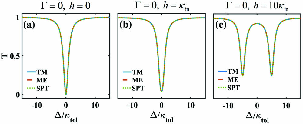
Fig. 2. Transmission spectra of a waveguide coupled with a microresonator. The blue solid, red dashed, and green dotted curves are calculated by the TM, ME, and SPT methods, respectively. The settings in the following figures are the same: (a) in the absence of backscattering, (b) and (c) in presence of the backscattering with strengths h = κin and h = 10κin, respectively. See Sec. 3 for other parameters.
Fig. 3. Transmission spectra for a chiral QE-microresonator system without considering the backscattering: (a)–(c) Γ = 0.1γ, Γ = γ, and Γ = 100γ, respectively.
Fig. 4. Transmission spectra for a chiral QE-microresonator system with the QE and the scatterer: (a) Γ = 100γ, h = κin and (b) Γ = 100γ, h = 10κin.
Fig. 5. (a) Transmission spectra for different driving amplitudes αin (corresponding to different pump powers), where the blue solid curve is calculated by the TM method, and the green dash-dotted curve (the red dashed curve, the purple dotted curve) is calculated by the ME method, with


Set citation alerts for the article
Please enter your email address

© Copyright 2018-2021 | Chinese Laser Press. All Rights Reserved 沪ICP备15018463号-20