• Chinese Optics Letters
  • Vol. 21, Issue 3, 031301 (2023)
Yan Wu1, Yang Yang2, Yue Yin1, Linmao Dai2, Xiaochun Li2, Huihui Huang1、*, and Shuangchun Wen1
Author Affiliations
  • 1Key Laboratory for Micro/Nano Optoelectronic Devices of Ministry of Education and Hunan Provincial Key Laboratory of Low-Dimensional Structural Physics and Devices, School of Physics and Electronics, Hunan University, Changsha 410082, China
  • 2Shenzhen Lubon Technology Co., Ltd., Shenzhen 518000, China
  • show less
    DOI: 10.3788/COL202321.031301 Cite this Article Set citation alerts
    Yan Wu, Yang Yang, Yue Yin, Linmao Dai, Xiaochun Li, Huihui Huang, Shuangchun Wen. Flexible high-resolution thin micropolarizers for imaging polarimetry[J]. Chinese Optics Letters, 2023, 21(3): 031301 Copy Citation Text show less
    Schematic diagram of the preparation process of a flexible high-resolution patterned polarizer. (a) Photoalignment layer is spin-coated onto a quartz substrate. (b) Regions of the photoalignment layer are aligned using laser writing. (c) Liquid crystal precursor is spin-coated on top of SD1. (d) Spin-coated AD1s solution; (e) spin-coated PDMS; (f) flexible patterned polarizer.
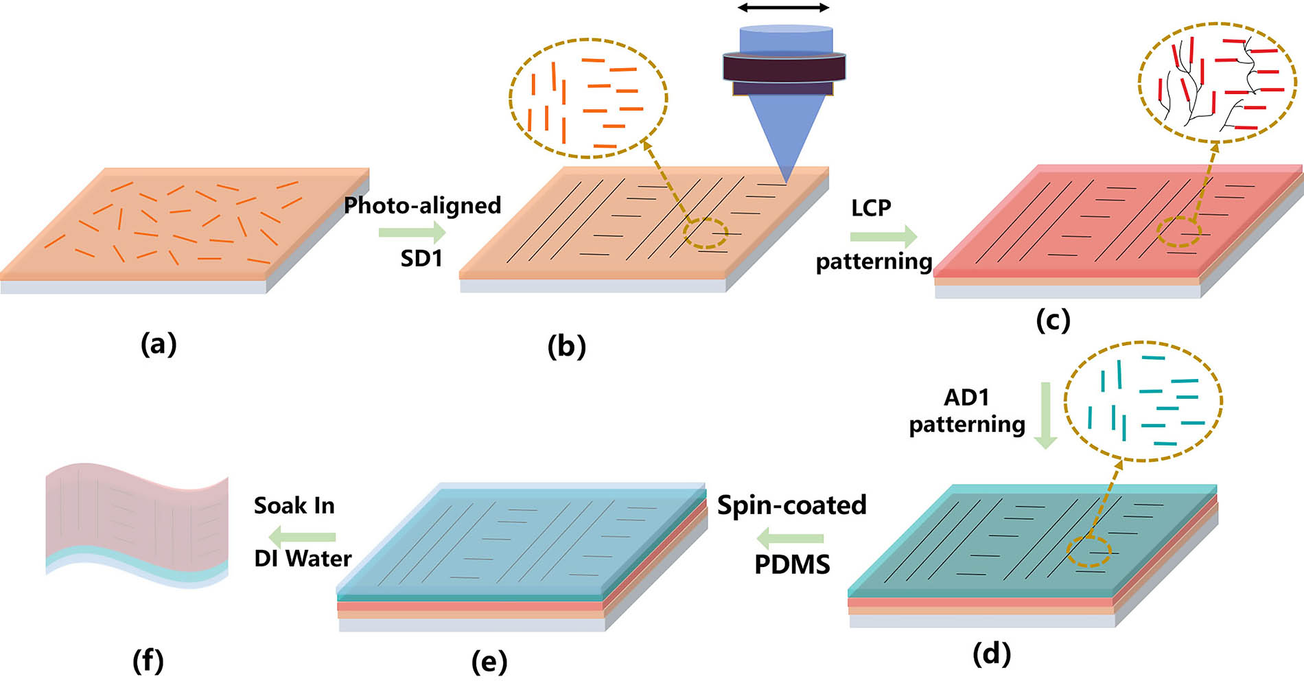
    Fig. 1. Schematic diagram of the preparation process of a flexible high-resolution patterned polarizer. (a) Photoalignment layer is spin-coated onto a quartz substrate. (b) Regions of the photoalignment layer are aligned using laser writing. (c) Liquid crystal precursor is spin-coated on top of SD1. (d) Spin-coated AD1s solution; (e) spin-coated PDMS; (f) flexible patterned polarizer.
    Photograph of a mixture film of liquid crystal and azo dye observed between a pair of crossed polarizers. (a) Before UV curing and (b) after UV curing. The physical picture of the polarizer when the polarization direction of the analyzed polarizer is (c) 0° and (d) 90°. The arrow indicates the direction of polarization of the analyzed polarizer. (e) Surface topography of the AD1 thin film with a thickness of 700 nm; the RMS of the roughness in a 2 µm × 2 µm area is 0.205 nm. (f) Cross-sectional SEM image of the polarizer on a glass substrate.
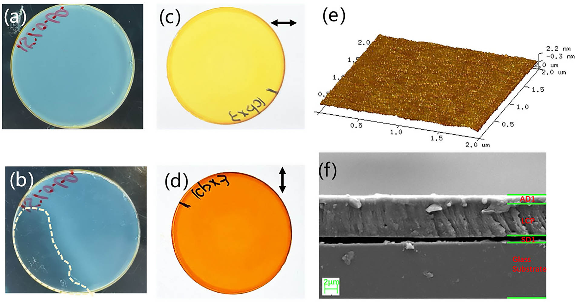
    Fig. 2. Photograph of a mixture film of liquid crystal and azo dye observed between a pair of crossed polarizers. (a) Before UV curing and (b) after UV curing. The physical picture of the polarizer when the polarization direction of the analyzed polarizer is (c) 0° and (d) 90°. The arrow indicates the direction of polarization of the analyzed polarizer. (e) Surface topography of the AD1 thin film with a thickness of 700 nm; the RMS of the roughness in a 2 µm × 2 µm area is 0.205 nm. (f) Cross-sectional SEM image of the polarizer on a glass substrate.
    (a) Extinction ratio test equipment for the dichroic-oriented polarizer. (b) Transmitted light intensity dependence on the rotation angle of the analyzing polarizer shows an extinction ratio of 336:1 for the aligned AD1, as indicated by the blue diamonds, with solid lines representing the cos2 fit. (c) Extinction ratio of polarizer versus number of LCP layers.
    Fig. 3. (a) Extinction ratio test equipment for the dichroic-oriented polarizer. (b) Transmitted light intensity dependence on the rotation angle of the analyzing polarizer shows an extinction ratio of 336:1 for the aligned AD1, as indicated by the blue diamonds, with solid lines representing the cos2 fit. (c) Extinction ratio of polarizer versus number of LCP layers.
    Polarized optical microscope image of azo dye film on (a) one LCP layer; (b) two LCP layers; (c) three LCP layers; (d) four LCP layers; (e) five LCP layers; (f) six LCP layers, respectively. Scale bar, 100 µm.
    Fig. 4. Polarized optical microscope image of azo dye film on (a) one LCP layer; (b) two LCP layers; (c) three LCP layers; (d) four LCP layers; (e) five LCP layers; (f) six LCP layers, respectively. Scale bar, 100 µm.
    Microphotographs of the fabricated grating-structured polarizing film magnified 100 times, with (a) 0°, (b) 45°, (c) 90°, (d) 135° linear polarizer on top; scale bar, 2 µm. The yellow double arrows show the molecular orientation of the azo dye, and the black double arrows show the orientation of the analytical polarizer. Microphotographs of the fabricated checkerboard-structured polarizing film, with (e) 0° and (f) 90° linear polarizer on top.
    Fig. 5. Microphotographs of the fabricated grating-structured polarizing film magnified 100 times, with (a) 0°, (b) 45°, (c) 90°, (d) 135° linear polarizer on top; scale bar, 2 µm. The yellow double arrows show the molecular orientation of the azo dye, and the black double arrows show the orientation of the analytical polarizer. Microphotographs of the fabricated checkerboard-structured polarizing film, with (e) 0° and (f) 90° linear polarizer on top.
    Image of patterned AD1 on the bendable LCP film with (a) 0°, (b) 90°linear polarizer on top. (c) Normalized extinction ratio of the flexible polarizer versus the number of bending cycles at a radius of 1 mm, and the folding angle ranges from 180° AD1 (illustration on the left) to 0° (illustration on the right). The gray line represents the best fit.
    Fig. 6. Image of patterned AD1 on the bendable LCP film with (a) 0°, (b) 90°linear polarizer on top. (c) Normalized extinction ratio of the flexible polarizer versus the number of bending cycles at a radius of 1 mm, and the folding angle ranges from 180° AD1 (illustration on the left) to 0° (illustration on the right). The gray line represents the best fit.
    Yan Wu, Yang Yang, Yue Yin, Linmao Dai, Xiaochun Li, Huihui Huang, Shuangchun Wen. Flexible high-resolution thin micropolarizers for imaging polarimetry[J]. Chinese Optics Letters, 2023, 21(3): 031301
    Download Citation